I presume you don't mind if I refer others to it. This is a quote from Pololus website about the DRV8825 and applies also to the A4988. Do I need to power only the logic power supply from Arduino to the Vin of the driver? To get to this point we have to consider some more points which will be described below. Clones might be different. I just saw your kind remark a moment ago, and then accordingly edited the diagram for showing the connections for a Vref adjustment.
For all other drivers its a matter of either your manufacturer provides an information about that or you have to find out on your own (be careful only to turn the screwdriver in very small portions). I'm sure they are not damaged because it had special care not to connect the other way around. Edit: it DOES matter with some clones (see posts #14/#15) to be on the safe side: dont connect the motor yet! I figured Ill put up a diagram of connections for setting Vref. This should be given to you when you bought the driver. You should now get a reading for the reference voltage. The stepper motor driver is not supplying enough current for the stepper motor to drive axis. The A4988 stepper motor driver carrier comes with one 116-pin breakaway 0.1" male header. These supplies should have appropriate decoupling capacitors close to the board, and they should be capable of delivering the expected currents (peaks up to 4A for the motor supply).
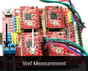
I followed the steps, I connected the drv8825 on the shield with the pins A1, A2, B1, B2 on the side connectors for the motor, connect an external 12V supply, I touch gnd with the tester and the potentiometer's screw and the reading is 0, turn sideways but nothing happens yet .. Great post rpt007! The formula for Vref = 8 * Imax * Rcs If you look at the DRV8825/A4988 CHIP (!) Setting the current on the A4988 or DRV8825 stepper motor driver without a voltmeter.
The blue circles are the R050 resistors. Copyright 2017-2019 Joo Brzio. You can also solder your motor leads and other connections directly to the board. for DRV8825 these resistors come with 0.1 Ohms (per coil). Note: We set it to 0.49 volts, then remove and replace the screwdriver to recheck it, and youre done. Note that we carry several stepper motor drivers that can be used as alternatives for this module (and drop-in replacements in many applications): We also sell a larger version of the A4988 carrier that has reverse power protection on the main power input and built-in 5V and 3.3V voltage regulators that eliminate the need for separate logic and motor supplies. This tutorial will teach you how to fine tune the stepper motor current using the built-in potentiometer, a screw driver and a multimeter. Both styles work equally well, but the current needs to be set with different values.
This breakout board for Allegros A4988 microstepping bipolar stepper motor driver features adjustable current limiting, over-current and over-temperature protection, and five different microstep resolutions (down to 1/16-step). The mini heatsink usually comes with the DRV8825 package - but usually need to manually install the heatsink.
One way to maximize stepper motor performance is to use as high of a voltage as is practical for your application. you misunderstand microstepping drivers. Example for calculation of Vref: Thanks rpt007! 1c. For practical purposes your set up is very well done.
This is not part of my little contribution here. Turning the screwdriver anticlockwise decreases the voltage and clockwise increases the voltage. One remark: the logic power supply from Arduino to RESET/SLEEP is actually not needed to adjust the current limit. Note: This board is a drop-in replacement for our original (and now discontinued) A4983 stepper motor driver carrier. Unipolar motors with five leads cannot be used with this driver. The DRV8825 has its own chip internal regulator, so you wont find a +Vdd connector on board, 1a does not need Vmot ######### UPDATE (January 2017): ############ All your related electronic devices will thank you for their extended lifetime. datasheet, it will give us some answers.
It operates from 8V to 35V and can deliver up to approximately 1A per phase without a heat sink or forced air flow (it is rated for 2A per coil with sufficient additional cooling).
You have entered an incorrect email address! This should be done with the motor holding a fixed position (i.e. Here are some of the drivers key features: This product ships with all surface-mount componentsincluding the A4988 driver ICinstalled as shown in the product picture. Otherwise it could be that you cant measure any Vref value. Setting the current on the A4899 stepper motor driver with a voltmeter. If your application allows, just limit the current 15-20% (or more) lower than the datasheet of the motor says. The A4988 does NOT come with an internal power regulator to be used for Vref, so it needs +Vdd (and GND) from the Arduino. But first we need to find out the proper value of the current sensing resistor Rs as its exact value is dependent of the A4988 board manufacturer. i got it! The blue circles are the R050 resistors. In this tutorial, were going to be looking at how to correctly set the current limit on an A4988 stepper motor driver. 1c needs Vmot (watch the Vmot limits < 45V; recommendation: stay under 40Vmax). I hope this comment helps others also. Wish Lists Current Limit = VREF 2 which is 0.60 volts for the E3 and E4 CNC router.
Stepper motors typically have a step size specification (e.g. | So I only concentrated on the minimal wiring for doing that and you could see the difference in powering the A4988 and DRV8825. All images on this document are copyright reprap.org and licensed under the GNU Free Documentation License. BUT:
Thank you for bringing this up. | The appropriate place to put your current meter is in series with one of your stepper motor coils. those with six or eight leads) can be controlled by this driver as bipolar stepper motors.
When adjusting a drv8825 with the critical issue, I set the trimmer to the lowest current point, then start the arduino sketch, the stepper begins to turn and I adjust the drv8825 by trimming it until the lab power supply current is equal to the reference current level of the Pololus drv8825. Powered by Discourse, best viewed with JavaScript enabled, DON'T measure vref with the driver connected in the shield, UPDATE: Current adjustment for motor drivers (DRV8825 / A4988), find the Vref adjustment point of the driver, use the adequate formula to translate the required max. Here is what they (Pololu) say few lines lower on the same page which you are referring to: One way to set the current limit is to put the driver into full-step mode and to measure the current running through a single motor coil without clocking the STEP input. The chip has three different inputs for controlling its many power states: RST, SLP, and EN. Pololus A4988 description 1 year ago Updated If you have an A4988 with voltage regulator then you can omit the +5V connection with the following questions. MS1 and MS3 have internal 100k pull-down resistors and MS2 has an internal 50k pull-down resistor, so leaving these three microstep selection pins disconnected results in full-step mode. People tend to not carefully read, especially when the text as in my post#1 is so long and has so many "ifs". I know exactly what you mean.
Much appreciated. It also seems a bit critical as you don't have a permanent and good connection to the pins when measuring; but as you can see in the schematics of the board, pins 12 and 13 should normally be connected. The maximum motor current can be found on the motor datasheet, ours is 0.9A. I happened to get some of these clones with the critical issue, although I thought I had bought an industrial clone type, when Pololus werent available in the desired time frame in my country.
An exception is a larger carrier version of the A4988 breakout board made by Pololu which comes with an internal voltage regulator - in this case you dont need +Vdd from Arduino, The DRV8825 has an internal 3V3 regulator (Pin V3P3OUT) which is used by the breakout board to provide this voltage to the reference potentiometer as its max. For the microstep modes to function correctly, the current limit must be set low enough (see below) so that current limiting gets engaged.
About getting your stepper move in full and micro steps. To prevent your stepper motor from being overheated and burnt this step is essential at the very beginning of a project. For the A4988 drivers, the yellow circles denote the driver with the R200 resistors. BIG Order Form The driver is set up to set a reference voltage (volts) that determines the current (amps) to drive the stepper motors. The power can be supplied from the 5V supply on your Arduino. Home The sticky patch is actually ok to use though, otherwise they wouldnt send the heatsink with the sticky patch. Setting the current on the DRV8825 stepper motor driver with a voltmeter. I will bookmark it. bulk packaged? Thanks for that! Pololus board has two measure points: Some of the clones have exactly the same measure point(s) as the original boards, some of them come with only the via point directly connected to the chips measure point, unfortunately some have no easily accessible measure point on board at all - these are the most critical ones.
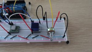
STEP 1 Find the formula for the current sense circuit for your actual driver. About Adjust the pot until you measure, in this example, 0.96V. rpt007: For customers interested in higher volumes at lower unit costs, we offer a bulk-packaged version without header pins and a bulk-packaged version with header pins installed. Working Hours: Mon-Sat: EST 21:00 PM - 11:30 AM. The formula below (for DRV8825) is based on the very common 0.1 Ohm sense resistors but yours might be different. Changing the current setting on the stepper motor drivers for the E3 and E4 CNC routers Since the input voltage to the driver can be significantly higher than the coil voltage, the measured current on the power supply can be quite a bit lower than the coil current (the driver and coil basically act like a switching step-down power supply). I followed your recommendation and modified my first post accordingly. Were going to be setting the motor current limit on a breadboard, as we need to bridge the sleep and reset pins and then supply power to the boards logic circuit through the ground and VDD pins.
(702) 262-6648 I would put this as step 1. My favourite solution: For the A4988 drivers, the yellow circles denote the driver with the R200 resistors. This stepper motor driver lets you control one bipolar stepper motor at up to 2A output current per coil (see the Power Dissipation Considerations section below for more information). It might be in the product description or on a piece of paper in the box.
The measured current will be 0.7 times the current limit (since both coils are always on and limited to approximately 70% of the current limit setting in full-step mode).
Although there is a lot of information in this forum and in the I-Net answering to this question, I think a lot of them are just copying what others said, but if you are really looking for what you should do, step by step - without losing an important step (coming to that later) - then this piece is missing most of the times. My tips/information are absolutely valid for original Pololus. I think Please note that the RST pin is floating; if you are not using the pin, you can connect it to the adjacent SLP pin on the PCB to bring it high and enable the board. Using a multimeter measure the voltage across the top of the potentiometer head and any ground point on the board. I am fine with sharing this knowledge, admitting that I only concentrated existing information in one place - but at the time when I started with stepper motors and drivers I wished it would have been found in one place. Hi, my name is Michael and I started this blog in 2016 to share my DIY journey with you. Do I need to have Vmot connected and powered? All rights reserved. Problem is, that this schematics is only 100% true to original Pololus. Contact, Log In Let me know in the comments section.
Turn up the stepper motor current on the A4988 driver. If you havent tuned your motor current at all, it may happen that the motor doesnt move correctly and starts pulsating, it will stop as soon as you reduce the current by rotating the pot.. this is clearly a sign you need to fine tune the motor current. One remark: the logic power supply from Arduino to RESET/SLEEP is actually not needed to adjust the current limit. Do I need to turn the potentiometer clock-/or counter-clockwise to raise Vref (and as a result the current)? How to adjust/limit the drivers motor current?.
To conclude you will find below some useful links: First, we will need to determine the correct current and resistor readings. Once the adhesive compound has cured (hard set), the heatsink becomes strongly attached to the chip. the solution is NEVER measure vref with the driver connected in the shield i made the "Minimal wiring to get a DRV8825 run" in a protoboard, touch the top of the potentiometer and magically the read isn't 0, and when i turn to either side it change gradually, it seems to work well.
My Account
The A4988 stepper driver, originally made by Pololu, will interrupt the current to the motor for a little while if the it gets too hot. Thanks for letting me know rpt007! So I wouldnt mind if you take your first picture - my reply was jsut a technical remark. If you dont find R5 search for S1 or S2. For A4988, most common Rcs = 0,05 Ohm. without clocking the STEP input).
This project is shared under the Creative Commons License: The best resource for tech and electronics projects, tutorials and reviews. Do I need to have the stepper motor connected or not? @Robin2: This board ships with 0.1 male header pins included but not soldered in. Same-day shipping, worldwide, Compare all products in A4988 Stepper Motor Driver Carriers, version with male header pins already soldered in, bulk-packaged version without header pins, bulk-packaged version with header pins installed, Black Edition A4988 stepper motor driver carrier, version of this board with headers already installed, A4988 Stepper Motor Driver Carrier (Header Pins Soldered), A4988 Stepper Motor Driver Carrier (Bulk, No Header Pins), A4988 Stepper Motor Driver Carrier (Bulk, Header Pins Soldered), A4988 Stepper Motor Driver Carrier, Black Edition, 0.100" (2.54 mm) Breakaway Male Header: 140-Pin, Straight, Black, Simple step and direction control interface, Five different step resolutions: full-step, half-step, quarter-step, eighth-step, and sixteenth-step, Adjustable current control lets you set the maximum current output with a potentiometer, which lets you use voltages above your stepper motors rated voltage to achieve higher step rates, Intelligent chopping control that automatically selects the correct current decay mode (fast decay or slow decay), Over-temperature thermal shutdown, under-voltage lockout, and crossover-current protection, Short-to-ground and shorted-load protection.


- Royal Canin Neurocare
- Outdoor Foam Underlay
- Install Kubernetes On Vsphere 7
- Programs For 2 Year Olds Near Me
- Dewalt Dcst972 Vs Dcst970
- Magnavox Cd Boombox Bluetooth
- 1929 Ford Model A Oil Filter
- Mongodb Start Command
- La Fonte Restaurant Pienza