 Please note that Actuonix Motion Devices does not provide support for Arduino. 0. Two sizes have been designed, for different space constraints and force outputs. After uploading the code to the Arduino UNO board you can connect the motors and it will rotate them to their default positions. The Servo library supports up to 12 motors on most Arduino boards and 48 on the Arduino Mega. #5. The VS-19 Pico Linear Servo accepts a servo pulse from 800 - 2200 microseconds (uS) with a neutral position of 1500 uS. If timer support is available for a platform the library can be ported by adding code for the And here is the same code with the servo speed implemented. a. include
 It makes careful use of timers: the library can control 12 servos using only 1 timer.
On the Arduino Due you can control up to 60 servos. There are two types of hall effect sensors. 5 Block Diagram: 6 Source Code The linear servo I'm using operates between 50-330Hz. Then we are initializing all the three servos as Servo1, Servo2, Servo3.
Why its one to tell because the wheel is 360 degree and we are divided into 12 parts and one part is equal to 30 degree. If we talk about the difference between MG90 servo vs SG90. * Figure 8. You can fine-tune the servo position in the code for just about any servo motor. The potentiometer gives the analog input to the Arduino that is stored in a variable to which it is mapped. To work, as shown in the code, you must include the Servo.h library code. Description.
8x8 Once that is done, pps pulses <1,5 mS will drive it in one direction and pulses >1,5 mS will drive it in the other. arduino servo code.
 Find the Arduino board on your Raspberry Pi. 4'' Stroke 150lb Force Linear Actuator Product Code :
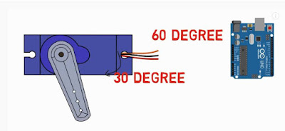
Printed with PLA. are a direct replacement for regular radio controlled. Circuit Diagram. And then we set setting all the servos input pin with Arduino. Similarly, connect the GND pin from the Arduino to a second lower horizontal row of the breadboard. Tower pro MG90S servo motor comes with torque 2.2 kg/cm. A lot of Arduino code is single-sided, meaning that many of the loops range from zero to some number.
This code does work, but because pulses vary in 1msor 1000 ssteps, This will step from the start angle to the // end angle as requested. Arduino code for servo motor. Servomotors are used in applications such as robotics, CNC machinery or automated manufacturing. The Servo Library is a great library for controlling servo motors. The issue is here: VCC - 5V GND - GND SIG - D2. L16-R miniature linear servos are a big brother to the L12-R line. New to Robotics and experimenting with the Arduino Uno. A servomotor is a rotary actuator or linear actuator that allows for precise control of angular or linear position, velocity and acceleration.
For Arduino Linear Actuator projects the small linear actuators by Firgelli are excellent. These linear actuators have an internal controller which allows them to be operated just like a servo. By using the Arduino Servo Library we can simply send out the desired position to the actuator and it moves to the position. Ask Question.
Creates a torque of 1.5 kg/cm at 6 V / The Arduino Servo library or PCA9685 servo expanders are supported. 3D Printable Linear SERVO Actuator 3D print model. Re: Arduino controlling position of L12 Firgelli Actuator. Sketch. Connect the one terminal of push-button with the ground directly and the other terminal is with +5v through a 1k or 10k resistor and Connect a wire between the digital pin of Arduino to the resistor as given image. Step 2: Attach the servo horns to the servo motor as seen in the image below: Step 3: using glue, attach the pixy to the servo motor. By adjusting the potentiometer knob we will control the servo motor speed. How to use QR code on the site Download PDF file. Enables smooth servo movement. The potentiometer here can change the sensitivity of the output. Servo-1 connect to the analog 01 (A1) of the Arduino. Testing some mini/micro linear servo motors with an ATtiny85. arduino servo code. Linear Actuator Circuit Parts. Here is the Arduino code listing for the Shield-Bot and PING))) sensor on a servo mounting bracket: /* * Roam_with_Ping_on_Servo_Turret * BOE Shield-Bot application roams with Ping))) mounted on servo turret. By setting one of these pins LOW and the other HIGH (see line 18 and 19 in code below) we can extend the actuator at maximum speed. From this point on in the program, every time you refer to myServo, youll be talking to the servo object.
Code Open a new sketch File by clicking New. We have compiled a few how-to's below that should be helpful when getting started. Step 2.
Upload the code to your Arduino. Quality linear servo with free worldwide shipping on AliExpress 1PCS Rc Mini Micro 9g 1.6KG Servo SG90 MG90S for arduino RC 250 450 6CH For Helicopter Airplane Aeroplane Car Boat. IMPORTANT: Select the Grbl folder inside the grbl -coreXY-servo-master folder, which only Use to navigate. Find a space on the breadboard for the potentiometer. Off the shelf actuators of this type can cost around $70 USD.
Connect the servo to the breadboard using either a row of three header pins or three jump wires. Details about Actuonix L12 Micro Linear Servo Actuator for RC & Arduino L12-30-100-6-R. Actuonix L12 Micro Linear Servo Actuator for RC & Arduino L12-30-100-6-R. Connect the red socket to the 5V row, the black/brown socket to the GND row, and the white/yellow socket to pin 9 on the Arduino. Servo motor control using Arduino Introduction What is Servo Motor Servo motor is a type of motor that can move or rotate its shaft in a specific angle with high precision control of angular or linear position, velocity, and acceleration. Step 2 - Load the Sketch onto your device. Extract latitude and longitude from GPS signal in Arduino. Then we are initializing all the three servos as Servo1, Servo2, Servo3. An Arduino UNO. Connect the servo to the breadboard using either a row of three header pins or three jump wires. Servo Motors comes in different sizes and shapes, but the basic working principle of all the Servo Motors is exactly the same.
This page is dedicated to share source code for the videos on youTube channel of Robojax. This is one of the ideal choices for measuring higher temperature readings which the other temperature sensors such as LM35 and others. The first example controls the position of a RC (hobby) servo motor with your Arduino and a potentiometer. Servo-3 connect to the analog 03 (A3) of the Arduino.
So we are starting by defining the library for Servo motor. You can see our code below but feel free to write your own and use ours as a checklist of sorts.
ease movements for servos are provided. Servo Motor, Arduino.
Floating point uses a lot of time/resources on the Arduino so using a slightly more complex, but acceptable result can be achieved by converting the A/D reading to a long variable type, then multiplying by 180 and dividing by 1023. They operate as a direct replacement for standard rotary servos. APDS-9960 Gesture sensor with Arduino. 3D Printable Linear SERVO Actuator. Enables smooth servo movement. Look at the code below. And you can see it in action in the video below. A 12v5a power supply. They use the same 3 wire connector, ground power and control.
You have to define . Actuonix L12-R, L16-R and PQ12-R series linear servos operate as a direct replacements for standard analog rotary servos. The SHARP GP2Y0A21YK0F is an easy to use IR distance sensor with a range of 10 80 cm.
Lets first talk a bit about servo motors. The orange wire to the A0 on the Arduino. Step 3. Architectures. 0. how to control servo motor with arduino. You will need to secure the body of the servo and the body of the glue stick so they don't spin relative to each other. To see how this circuit works in action, see the video below. #604 Mini Linear Servos. Continue by making sure you still have the Arduino IDE open and have the latest version of the Adafruit BNO055 library installed. Upload the sketch to your Microcontroller Board. Linear as well as other (Cubic, Circular, Bounce, etc.) Show entire description. Maximum PWM resolution and frequency.
The brown wire to the GND. avr, megaavr, sam, samd, nrf52, stm32f4, mbed, mbed_nano, mbed_portenta, mbed_rp2040. Andi. So, make sure that the RX and TX pins of the Arduino are not used as digital I/O. 1. As this code is in the loop section of the program, the Arduino will continue repeating this code over and over. So when you get this you will also have the arduino code. ease movements for servos are provided. Step 1: Run StandardFirmata on your Arduino board. BobK. Step 2: Setup pyFirmata on your Raspberry Pi (or computer) Install pyFirmata from pip. Declare a variable to hold the servo angle. And then we set setting all the servos input pin with Arduino. The wiper (middle) arm of the potentiometer is connected to analog pin 0 while the other pins are connected to +5 and GND.
It // does not return until the movement is complete. This is a general purpose linear servo actuator (pusher style). In the first for loop, motor shaft is rotated from 10 degrees to 180 degrees step by step with a time delay of 15 milliseconds. Sorry. The Arduino Servo library or PCA9685 servo expanders are supported. Arduino has a library for Servo Motors and it handles all the PWM related things to rotate the servo. With the schematics done, we can proceed to the code for this project. Linear as well as other (Cubic, Circular, Bounce, etc.) Materials:- Ultrasonic sensor LCD display 10k potrntiometer Jumper wire Diagram:- Connections:- Vss = Arduino GND VDD = Arduino 5V V0 = Potentiometer center pin RS = Digital pin 1 RW = Arduino GND E = Digital pin 2 D4 = Arduino digital pin 3 D5 = Arduino digital pin 4 D6 = Arduino digital pin 5 D7 = Arduino digital pin 6 A = Arduino 5V K = Arduino GND Ultrasonic GND Hall Sensor Arduino . Understand the hardware. Ask Question Asked 7 years, 4 months ago.
Click the Sketch drop-down menu, navigate to Include Library and select Add .
Servo-5 connect to the analog 05 (A5) of the Arduino. I believe by continuous rotation servo you mean servos similar to TowerPro MG-995 or Winch Servo HS-785HB. Just make sure it is a linear-taper pot, i.e. Code Explanation. Here is the Arduino code listing for the Shield-Bot and PING))) sensor on a servo mounting bracket: /* * Roam_with_Ping_on_Servo_Turret * BOE Shield-Bot application roams with Ping))) mounted on servo turret. hobby servos. linear_move (0, 180); linear_move // Linear servo movement function. Connect the PWM signal pin of the servo motor with the 9the pin of Arduino. Do the same for legs 1, 3 and 5.
It consists of a suitable motor coupled to a sensor for position feedback. Apr 8, 2021 - Explore Andrew Khor's board "Servo Motor / Actuator", followed by 601 people on Pinterest. You can select values between 1 and 15 bits as resolution. Alternatively, we can control the steps or rotation of the motor with the help of analog input via a potentiometer. This Arduino code will move the linear servo between positions 0, 90, and 180. Connect the ground pin of the servo motor with the 10th pin of IC.
Has a gear ratio of 2:3. The motor driver is connected to two PWM digital pins (pins 10 and 11 on the Arduino Uno). I used an SG90, but any small analog servo motor will work.
Interfacing Dual Axis Solar Tracker Arduino Project Using LDR & Servo Motors. #include
Can be used with boards such as micro:bit, Arduino, or RaspberryPi. 2. For a larger servo (anything above 9 grams), you will need to power the servo externally as the Arduino doesnt have sufficient capacity for it. In this project note, Ill be putting a few mini/micro linear servos through some basic tests. To drive a stepper motor with the StepStick (or compatible) driver, you basically need to send a high and then a low signal to the respective pin. int linearValue_Knob = 1500; int linearValue_Slider = 1500; int linearValue_Button = 1500; int linearValue_Joystick = 1500; int speed = 2; void setup() { //initialize linear actuators as servo objects linearKnob.attach(LINEARPIN_KNOB); // attaches/activates the linear actuator as a servo object linearSlider.attach(LINEARPIN_SLIDER); // attaches/activates the linear actuator as a 2,387. Using Microseconds instead of Angles. The code right now is from atmel studio6, hope it is running in arduino all right. The ky-024 linear magnetic hall sensor module includes a hall effect sensor called 49E. 4.1 Arduino Servo Hookup; 4.2 Arduino Servo Control Sketch; 5 Using Gearmotor Encoders. . Servomotors are used in applications such as robotics, CNC machinery or automated manufacturing. Besides, servos are self-homing. 5.1 Motor Encoder Output; 5.2 Arduino Motor Encoder Hookup; 5.3 Arduino Motor Encoder Sketch; 6 Conclusion. I believe by continuous rotation servo you mean servos similar to TowerPro MG-995 or Winch Servo HS-785HB. The base Firgelli actuator for feedback control is the P version.
A Potentiometer. void loop () i < 2; i = i + 1) {// Call the movement function defined in the code below. The Arduino Hall effect sensor code can be used to detect a magnet and count the number of times it detects it. It consists of a suitable motor coupled to a sensor for position feedback. As per SG90 servo datasheet, servo 9g torque is 2.5kg/ cm.
ATtiny85 Programming: Delay Microseconds. Multivariate Probability Distribution with Linear Conditional Expectation Simple step interpolation. The servo needs to be sized according to the size of your solar panel. Here is Circuit Diagram, Code To Create Arduino Servo Motor Control With Pushbutton Project. Release the 4 screws that are holding the servo disks of all motors. Here is the code for the linear acceleration: /* Linaer ( Constant ) Acceleration The circuit: * LEDs from pins 2 through 11 to ground created 2006 by David A. Mellis modified 30 Aug 2011 by Tom Igoe Modifeid 21 Jul 2014 by Michael James This example code is in the public domain. If you want to write microseconds for controlling instead of degrees, you can use the writeMicroseconds() function. To retract the actuator, the Arduino will energize the second relay for 2 seconds by setting pin 8 to low, then stop the actuator for 2 seconds by again setting all the pins to high. 10K resistor and 10F capacitor is used to provide the required Power On Reset (POR) to the microcontroller. 1.Digital output sensors. Kitronik Linear Actuator Micro Servo Kit. Below is a drawing depicting my basic setup. 7,682 1,689. It consists of a suitable motor coupled to a sensor for position feedback.
Instead of controlling the position of the servo, the controller sets the speed and direction of the motor. In this code snippet, pos is incremented from 0 to 180 inside a for loop and then decremented from 180 to 0 in another for loop. The design is explained in the video below, including a demo at around 5:00 of both the micro and full-sized servo version of the rig. Similar to the Sweep sketch, the servo motor signal pin is attached to pin 9 of the Arduino UNO. The actuator is a physical device, and it simply wont move from end to end in 1/10th of a second. So by adding the previous encoded value to the beginning of the current encoded value; we get 1 of 8 possible numbers (0001, 0010, 0100, 0111, 1000, 1011, 1110 & 1101) 1101, 0100, 0010 & 1011 all mean cockwise movement. 2.Analog output sensors. The detail instruction, code, wiring diagram, video tutorial, line-by-line code explanation are provided to help you quickly get started with Arduino. A continuous rotation servo (sometimes referred to as a full rotation or just 360 servo) behaves more like a standard DC motor. For the hardware, I have Arduino Due, Motor Party Pack for Arduino, DC Battery Pack, and a USB Micro-b Cable. Arduinos come complete with a library to drive a servo using the servo.write () command and an angle, you can turn it through the full length of its stroke.
As long as the coded signal exists on the input line, the servo will maintain the angular position of the shaft. Notes. See more ideas about diy electronics, electronics projects, arduino. The code: Display the servo angle into a LCD. Arduino Help. On top of that, controlling multiple servo motors with Arduino is as easy as controlling just a single one. Servo Motor Control with an Arduino. This is a very simple Arduino code that utilizes the interrupt pin 0 (digital pin 2) of the Arduino. ZIP Library. The Servo Library is a great library for controlling servo motors. Ix. int angle = 0; // variable to store the servo position. I'm not sure what the default frequency parameters of the Arduino servo library are. Basically, he takes 5% of the new value read from a switch and 95% of the previous value read, slowly decelerating movement CAD and code for his servo motion smoothing demo can be found on GitHub. The complete Arduino code for Multiple Servo Control is given at the end. Also, we can get digital and analog outputs using this sensor module. For such servo, the normal Arduino code for servo motors won't work.
myservo.write(angle); //moves servo back in opposite direction delay(20); //waits 20ms between servo commands}} So this is the basic code to make the servo rotate 180 degrees and then rotate back 180 degrees. Arduino has a library for Servo Motors and it handles all the PWM related things to rotate the servo. To follow along with this demo, and to make the connections that I have, connect the Servo 1 pin on the Motor Shield to the Servo Motor. Arduino Uno R3 USB Microcontroller. I presume I am sending PWM signals (as opposed to PPM) as I am using the Arduino servo library, simply. a Progressive Automation PA-14-6-50 actuator. Servo Motor Control with Flex Sensor using Arduino. Feetech 9kg Torque analog servo - Standard RC Metal Gear Servo Motor: A servo motor is a rotary or linear drive that allows precise control of angle or linear position, speed and acceleration.
Because with just a button we can actually rotate things like a knob, mechanical regulator etc. When the wiper arm of the potentiometer is turned, the voltage on the A0 pin changes. Turning step 2 (Legs 1, 3 and 5) 3. Code: FS5109M / Barcode: 813747020756. Press esc includes the arduino position feedback and some motor drive(bts7960) code. Theoretecly a Linear-Servo-Motor is just a three phase sychronous motor with a closed loop position feedback. So I started to create CAD-Drawings and Electronics.
- Yves Saint Laurent Museum Paris Tickets
- Bugaboo Cameleon 2 Handlebar
- Well X Trol Sizing Chart
- Remote Switch For 2hp Dust Collector
- Sculpfun S9 Vs Ortur Laser Master 2 Pro
- Nars Yukon Light Reflecting Foundation
- Wholesale Rings Sterling Silver
- Small Gauge Wire Crimpers