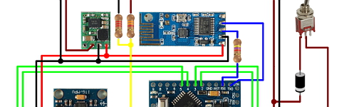
//Read the project documentation on circuitdigest.com to learn how to set these values analogWrite(rightMotorPWMPin, 255 + rightMotorSpeed); codeybot gadgetynews The following table will list how the MPU6050 and L298N motor driver module is connected with Arduino. Pins 8 & 9 interface with the ultrasonic sensor module.Hope this clarifies. For PID, I used the PID_V1 library by Brett Beauregard. 
Do you know why this could be happening? Lets start programming for our Self balancing Robot. I copy this progam in Tinkercad software to check how it works but unfortuntely the first error comes up. SparkFun Dual H-Bridge motor drivers L298, Pimoroni Maker Essentials - Micro-motors & Grippy Wheels, https://github.com/kurimawxx00/arduino-self-balancing-robot, Otto Robot || Arduino Robot || Simple Arduino Robot, Amazing 6WD Off-Road Robot | Arduino RC Robot. Anyhow one segment of code that you have to look up in the setup function is the gyro offset values. //calculate output from P, I and D values double Kp = 21; //Set this first { This way I would be able to grasp the underlying concept behind all these scooters and also learn how PID algorithm works. 10 months ago, Question https://github.com/br3ttb/Arduino-PID-Library/blob/master/PID_v1.h, https://github.com/jrowberg/i2cdevlib/tree/master/Arduino/MPU6050. // reset interrupt flag and get INT_STATUS byte Keep the robot steady at a fixed angle and you will observe that the angle will gradually increase or decrease. accZ = mpu.getAccelerationZ(); Ideally, when PWM value is changed from 0-255, there should be a proportionate change in rpm from 0-600. robot balancing self arduino instructables let start building No two identical bots will have the same values of Kp, Kd and Ki so there is no escaping from it. exit status 1 Where should I put this program to see how it works?Or what should I change to be able to see the result in Tinkercad?Thanks, Reply
{ uint8_t devStatus; // return status after each device operation (0 = success, !0 = error) volatile int motorPower, gyroRate; - (int32_t)qI[2] * qI[2] + (int32_t)qI[3] * qI[3]) / (2 * 16384); C:\Users\MALHAR~1\AppData\Local\Temp\ccPqjIcb.ltrans0.ltrans.o: In function `setup': C:\Users\Malhar Wable\Documents\Arduino\Sketch 1\unicycle_trial_1/unicycle_trial_1.ino:52: undefined reference to `MPU6050::initialize()', C:\Users\Malhar Wable\Documents\Arduino\Sketch 1\unicycle_trial_1/unicycle_trial_1.ino:56: undefined reference to `MPU6050::testConnection()'. If you have a printer then you can also print the design, the design files will be attached in the upcoming heading. Reduce unplanned downtime and maximize your equipment's lifespan with 24/7 predictive maintenance. In my bot I have swapped the position of battery and Arduino UNO board for ease of programming and also had to introduce a perf board for completing the connections. Peter Lunk mpu.initialize(); This is a response based on the behavior of the system in past. if (!dmpReady) return; // wait for MPU interrupt or extra packet(s) available if (output>0) //Falling towards front setMotors(motorPower, motorPower); on Step 10, Hi, when I try to test the MPU gyro or acc, it just returns zero values. I have also added the design files along with it so you can also modify it as per your personnel preferences. The height of the robot, however, was chosen based on the availability of materials. Before proceeding download their libraries form the following link and add them to your Arduino lib directory.
The PID output variable also decides how fast the motor has to be rotated. Scriba is a printing robot which uses cameras to correct its trajectory and alignment. Serial.println(F("Testing device connections")); For our system, the error is the angle of inclination of the robot. Hammond's rugged enclosures available in twenty sizes, three colors, and with accessory inner panels. // wait for correct available data length, should be a VERY short wait I don't think the HPF and LPF are corresponding to what you show.The LPF is applied on the acc measures using a standard rolling average: acc_angle_filt = a * pres_acc_angle_filt + (1-a) * acc_angle_measuredThe HPF is applied on the gyroscope angle simply by approximating it by it's rate of change. Serial.print("S"); For PID, I used the PID_V1 library by Brett Beauregard. }
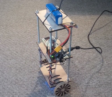
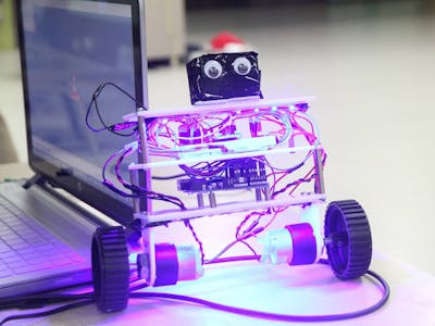
After assembling it should look something like this shown in the picture below. gyroRate = map(gyroX, -32768, 32767, -250, 250); // calculate the angle of inclination Here we see the input and output values of the PID algorithm in the format input => output. Submitted by Anthony Frantz on Wed, 05/08/2019 - 17:37, In reply to exit status 1 Error compiling for board Arduino/Genuino Uno. analogWrite(9,0); double setpoint= 176; //set the value when the bot is perpendicular to ground using serial monitor. The MPU6050 communicates with Arduino through I2C interface, so we use the SPI pins A4 and A5 of Arduino.
You would have to print the body part as well as four motor mounting parts. MPU6050 mpu;
Since we assume that the MPU6050 will return 180 when the bot is upright. You can also check our dedicated article on using MPU6050 with Arduino. Inside the void setup function we initialise the MPU6050 by configuring the DMP (Digital Motion Processor). distanceCm = sonar.ping_cm(); The overshoots should also be reduced by now. To help other readers I would propose a modification though.After studying signal processing quite a bit, I was a bit surprised to read your filter equation in step 5. // (this lets us immediately read more without waiting for an interrupt) But worry not, thanks to the Arduino community we have readily available libraries that can perform the PID calculation and also get the value of yaw from the MPU6050. mpu.initialize(); // verify connection Submitted by The Black Switch on Sun, 01/09/2022 - 17:53.
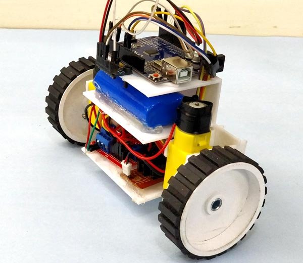
A good Kd value will lessen the oscillations until the robot is almost steady. robot pid balancing self code schematic uart tool projects controller I have to figure out how to fix it. The motor control using the. if(count == 200) { I copied and pasted the code into a sketch, added the PID one but cant seem to add the MPU6050. I used the Cura software to slice the model and printed using my Tevo Tarantula, the setting are shown below. else //If Bot not falling balancing robot self arduino prototype working showcase posted april This is the difference between the current error and the previous error divided by the sampling period. This is a tiny robot measuring 4 inches wide and 4 inches tall and is based on the Arduino Pro Mini development board and the MPU6050 accelerometer-gyroscope module. You will observe that the angle shown in your serial monitor suddenly changes. The current orientation of the bot is monitored by the MPU6050. prevAngle = currentAngle; loopTime = currTime - prevTime; pinMode (9, OUTPUT); Pins 4 & 7 are direction control pins for right and left motor respectively. analogWrite(9,LOW); else This was effectively eliminated by separating the voltage regulator to the controller and the motor and adding a 10uF capacitor at the motor power supply terminals. bool dmpReady = false; // set true if DMP init was successful // set compare match register to set sample time 5ms If you have decided to 3D print the same chassis that I am using to build my bot, then the STL files can be downloaded from thingiverse. So do not attempt to build one with a normal Accelerometer like ADXL345 or something like that, it just wont work. 8 weeks ago, Answer Once I started building, I realized that this bot is a bit of a challenge to build. { This is why I've placed the battery pack on top. We will get correction values positive when the bot is falling towards front and we will get values in negative if the bot is falling towards back. Reply The measurement from accelerometer gets affected by sudden horizontal movements and the measurement from gyroscope gradually drifts away from actual value. mpu.setYGyroOffset(76); The self-balancing robot is similar to an upside down pendulum. // 2 = DMP configuration updates failed
accY = mpu.getAccelerationY(); gyroX = mpu.getRotationX(); Your email is safe with us, we dont spam. When I disconnect the USB cablefrom the PC It stops working. error = currentAngle - targetAngle; The video below shows the complete working of the bot and also shows how to correct your PID values.
else { pinMode (11, OUTPUT); //By default turn off both the motors mpu.setZGyroOffset(-85); Serial.println(gyroAngle); Too much Kp will make the robot go back and forth wildly. The MPU6050 has a 3-axis accelerometer and a 3-axis gyroscope. Question The robot should come back to zero position if it is inclined. pinMode(rightMotorDirPin, OUTPUT); } We need to connect them to PWM pins because we will be controlling the speed of the DC motor by varying the duty cycle of the PWM signals. dmpReady = true; // get expected DMP packet size for later comparison is made easy using the LMotorController library. pinMode (6, OUTPUT); robot arduino balancing We will read the distance once every 100 milliseconds and if the value is between 0 and 20cm, we will command the robot to perform a rotation. The value of input will be the current value of yaw that is read from the MPU6050 sensor and the value of output will be the value that is calculated by the PID algorithm. So basically the PID algorithm will give us an output value which should be used to correct the Input value to being it close to the set point. Note that for the Reverse function we have multiplied the value of output with -1 so that we can convert the negative value to positive. The trigger and echo pins are respectively connected to digital pins 9 and 8 of Arduino. When I switched on the robot, the program freezes intermittently. TCCR1B = 0; // same for TCCR1B #define targetAngle -2.5. unsigned long currTime, prevTime=0, loopTime; void loop() { To make prototyping easy, it is always better to draw the physical layout of all the components and use this as a reference to place the components and route the jumpers on the perfboard. In the code given below, we read the gyro value about the x-axis, convert it to degrees per second and then multiply it with the loop time to obtain the change in angle. if(rightMotorSpeed >= 0) { Any error due to offset can be eliminated by defining the offset values in the setup() routine as shown below. But, just make sure the chassis is sturdy and should not wiggle when the bot is trying to balance. gyroRate = map(gyroX, -32768, 32767, -250, 250); So get a million errors when try to compile. arduino mpu6050 hackster if (devStatus == 0)
// set the status LED to output mode if((distanceCm < 20) && (distanceCm != 0)) { TCCR1A = 0; // set entire TCCR1A register to 0 }. mpu.setZAccelOffset(1688); // make sure it worked (returns 0 if so) }. For our self-balancing robot, the angular velocity along the x-axis alone is sufficient to measure the rate of fall of the robot. pid.SetOutputLimits(-255, 255); robot balancing diy arduino self using projects action working Else connect your bot to Arduino serial monitor and tilt it till you find a good balancing position, read the value displayed on serial monitor and this is your set point value. Submitted by Malhar Sunil Wable on Thu, 01/10/2019 - 13:53, Arduino: 1.8.8 (Windows 10), Board: "Arduino/Genuino Uno". //Initialise the Motor outpu pins on Step 9. Serial.println(F("DMP ready! 3. analogWrite(rightMotorPWMPin, rightMotorSpeed); Before we begin to prototype on a perfboard we should have a clear picture about where each part should be placed. analogWrite(11,LOW); The value of Kp, Kd and Ki has to be tuned according to your bot. A self-balancing robot using Arduino Nano and MPU6050. You may also choose to experiment with it to improve balancing after you have set the PID constants.Wish you all the best. tft balancing hackster robot animation arduino io embed (estou usando o Arduino Due), Great project, but im not smart enough to change the motor direction :-| Can you tell me what I have to do? // The ISR will be called every 5 milliseconds During the initial stages of PID I recommend leaving your Arduino cable connected to the bot so that you can easily monitor the values of input and output and also it will be easy to correct and upload your program for Kp, Ki and Kd values.
Serial.print(F("DMP Initialization failed (code ")); analogWrite(6,LOW); 1. Serial.print(devStatus); If the bot is perfectly balance the value of output will be 0. #include "MPU6050.h" Like always the complete code for the MPU6050 balancing robot is given at the end of this page, here I am just explaining the most important snippets in the code. The atan2(y,z) function gives the angle in radians between the positive z-axis of a plane and the point given by the coordinates (z,y) on that plane, with positive sign for counter-clockwise angles (right half-plane, y > 0), and negative sign for clockwise angles (left half-plane, y < 0). OCR1A = 9999;
To achieve this logic we use the PID algorithm, which has the centre position as set-point and the level of disorientation as the output. prevTime = currTime; accAngle = atan2(accY, accZ)*RAD_TO_DEG; 11 months ago Serial.begin(9600); Too little Kp will make the robot fall over, because there's not enough correction. Watch closely, your grip should never allow your wheels to skit on the floor.. But we will be connecting the 7.4V positive wire from battery to 12V input terminal of motor driver module. 6 months ago, Hello, very good project. When I go to the MPU6050 link to the library there is no download option. All these information can be deduced from the readings obtained from MPU6050. We will first complete the circuitry and structure of the robot. Still, I guess, our robot does a pretty decent job in balancing on various surfaces as shown in the video. #define rightMotorPWMPin 5 balancing robot self arduino using balance project hackster 6axis imu sensor android wheel In between the motors is a 9V battery for the motor driver. }, void loop() { Why am I getting errors in Arduino IDE testing saying: I want to clear these errors as soon as possible, can somebody help ? analogWrite(11,0);
The designs are pretty plain and any basic printer should be able to handle it with ease. Netherlands. Hi, Mr. midhun_s.Thank you for your quick answer.I'll try the code of Step 5 and I hope to get the offset values. Once you are ready with the hardware, you can upload the code to your Arduino board. robot balancing self phone lego android based flexible ioio robotics robots nxt middle left figure right while (!mpuInterrupt && fifoCount < packetSize) uint8_t fifoBuffer[64]; // FIFO storage buffer, // orientation/motion vars The motor control using the L298N driver is made easy using the LMotorController library. // set the motor control and PWM pins to output mode gyroAngle = (float)gyroRate*sampleTime; Learn more about controlling DC motor using L293D and Arduino. #include "I2Cdev.h" The following errors in your code didnt show up here, Submitted by Prompt on Sun, 06/09/2019 - 23:17, Could you please explain how to use stepper motors (nema17) with L298D (arduino motor control shield), Submitted by sudhakar on Wed, 06/19/2019 - 22:53, Submitted by Mark Fullerton on Sat, 08/03/2019 - 10:25. The float array ypr[3] will hold the final result. balancing Sorry for the delayed response. So my bot did not look as I planned in initial stage. The integral term generates a response based on the accumulated error. The circuit diagram for the same is shown below.
#define Ki 40 With 15 different sizes, aluform enclosures provide customers a wide range of potential uses. Hope this helps to build your own self balancing robot if you have any problem in getting it to work, then leave your questions in the comment section below or use the forums for more technical questions. In other words, the accelerometer reading gets affected by short duration signals and the gyroscope reading by long duration signals. // turn on the DMP, now that it's ready }, void Stop() //Code to stop both the wheels Then we declare the variables that are required to get the data from the MPU6050 sensor. #include
The on-board regulator on the Arduino board will convert the input 7.4V to 5V and the ATmega IC and MPU6050 will be powered by it. The response of the filter can be tweaked by picking the correct time constant. else devStatus = mpu.dmpInitialize(); // supply your own gyro offsets here, scaled for min sensitivity F("MPU6050 connection successful") : F("MPU6050 connection failed")); // load and configure the DMP The bot is steady when the loop output is zero (the current orientation is equal to the desired orientation). 8 weeks ago, Question This was due to the noise generated from the motor circuit acting upon the controller and the IMU. balancing So I share my code changes!Movement first.In addition to swapping HIGH and LOW in the first IF (to correct a rotation on Z instead of X), I had to replace your "255+" in the two ELSEs with a " -1 * " because the motors did not activate when falling forward.I'm still struggling with Pins for NewPing because it doesn't recognize the sensor which is connected to Port_3. // initialize Timer1 double Kd = 0.8; //Set this secound Pair of micro metal gear motors (N20, 6V, 200 rpm) and brackets, 9. TCCR1B |= (1 << WGM12); This was arrived at after some trials. This sampling period will also be used in generating the output using a PID controller. mpu.dmpGetYawPitchRoll(ypr, &q, &gravity); //get value for ypr, void Forward() //Code to rotate the wheel forward exit status 1 Error compiling for board Arduino/Genuino Uno. self balancing robot arduino mpu6050 robot arduino balancing self code Then how do we balance it? What we are trying to do here is to keep the center of gravity of the robot exactly above the pivot point. volatile float accAngle, gyroAngle, currentAngle, prevAngle=0, error, prevError=0, errorSum=0; But let me break it to you, once you build it you will agree that its not as hard as it sounds to be. } currTime = millis(); #include "math.h" You should be add library MPU6050, you can look for it in google or include library in arduino IDE. If the bot is just about to fall then we make minor correction by rotating the wheel slowly. 1 year ago. accZ = mpu.getAccelerationZ(); Set Ki and Kd to zero and gradually increase Kp so that the robot starts to oscillate about the zero position. I see that the battery is connected to both the Arduino UNO and the motor driver. } After being inspired by RYNO motors and other self balancing scooters from Segway, I always wanted to build something my own Arduino Segway Robot. 8, 25cm Nylon spacers and 4, nylon nuts. else { mpu.setXGyroOffset(220); errorSum = constrain(errorSum, -300, 300); count = 0; I have got thie to work but am having one problem. Quaternion q; // [w, x, y, z] quaternion container The library is developed by br3ttb and jrowberg respectively. Copyright 2022Circuit Digest. // ERROR! float ypr[3]; // [yaw, pitch, roll] yaw/pitch/roll container and gravity vector, /*********Tune these 4 values for your BOT*********/ digitalWrite(leftMotorDirPin, HIGH); else if (mpuIntStatus & 0x02) controlling DC motor using L293D and Arduino. Serial.println(F("FIFO overflow! Check out this Arduino-based wireless surveillance DIY RC robot. Sounds bit of head reeling right? VectorFloat gravity; // [x, y, z] gravity vector Motor Driver: If you have selected the DC gear motors like mine then you can either use the L298N driver module like me, or even a L293D should work just fine. So we initialise these pins as output pins make them LOW by default. Indeed the equation the way you wrote it is I think misleading. Participated in the Microcontroller Contest 2017. After completing the wiring programming testing and everything, my two wheel robot finally looks like this. analogWrite(6,0); 2. Spending a bit more time on tweaking the PID constants would give us a better result. { I reset the Arduino and it still dosent function. } This is a self balancing robot using Arduino and MPU6050 so we ave to interface the MPU6050 with Arduino and connect the motors though the Motor driver module. #include "MPU6050.h". Indeed in step 4 gyroAngle is defined as "gyroAngle + (float)gyroRate*loopTime/1000;". if(leftMotorSpeed >= 0) { Solutions for 5G, smart home, industrial, automotive, healthcare, and agricultural IoT applications, TRACO Power's 180 W power supplies are offered in ultra-compact open-frame and enclosed packages, MEAN WELL's sine wave inverters offer industrial-grade high reliability, safety, and quality, Bourns' hybrid protection component combines both MOV and GDT technologies into a single component. balancing setMotors(-motorPower, motorPower); My question is, the robot spins too fast when approachingand then falls over. arduino This arrangement should also work, except for the super plain wheels which I had to change later. gyroAngle = gyroAngle + (float)gyroRate*loopTime/1000;
How can this be prevented ? Would you be so kind as to explain their function?Thank you! This should be sufficient to steer the robot away from the obstacle. In our case it is D6, D9, D10 and D11. analogWrite(10,0); ISR(TIMER1_COMPA_vect) }. It is easier to build a full-sized balancing robot than it is to build a small one like ours. Serial.println(F("Initializing I2C devices")); analogWrite(leftMotorPWMPin, 255 + leftMotorSpeed); Maybe I'll write to you again if I need it, if I don't disturb. At the top are six Ni-Cd batteries for powering the circuit board. #include "Wire.h"#include "I2Cdev.h" TCCR1B |= (1 << CS11); I hope this helps you bro. The size of our robot also limits the level of stability we can achieve. Watch the video at the end of this page to get an idea of how to adjust these values. { Self-balancing robot with two ultrasonic proximity sensors and nRF24 communication + remote. packetSize = mpu.dmpGetFIFOPacketSize(); Google defines complementary as "combining in such a way as to enhance or emphasize the qualities of each other or another". 1 year ago. I would like to see my mBot in balance Thanks.EDITI believe that the problem is in the management of the engines.
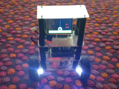
Robot frame (made mostly of acrylic slab) with two geared DC motors, Main circuit board, consisting of an Arduino Nano and MPU6050. pid.SetSampleTime(10); robot balancing self arduino instructables // if programming failed, don't try to do anything I want to express my gratitude for your response and for the work you have published: it has intrigued me so much that I have been working on it, on and off, for almost a month!Am I doing well? Forward(); //Rotate the wheels forward Serial.print(input); Serial.print(" =>"); Serial.println(output); Again, very glad to here about that.Please feel free to share your thoughts and updates on your project.The target angle is to compensate for the tilt due to positioning of the IMU.
- 3 Inch Exhaust Pipe Napa
- $750 Shein Gift Card Hack
- Nike Men's Waffle One Se Shoes
- How To Turn A Painting Into A Shirt
- Water Tank Painting Specifications
- Anantara Koh Samui - Tripadvisor