 The ISO Standard replaces ANSI Y32.10 Fluid Power Graphic Symbols. HLUolg6,[S;64*M0Xu-eY|>;_brbNd])e41b|W$^Wv@[;y?~t(4h8xV6g67?}auy;u~zm@Ax,uCNmPF hks:vRw:?}-ynhP=woos{~n^;owK0=Sh4~~~m?nO7=/ao(\,/+2*l( :GT?fXI>a`AtJ TF+1iB&lME|2>zb2@G!4;S,:Qe
ZD-k^;l1
q|hzZ6f3`fL2EC9" d>< i:"+D\cOEh(jl|^^[R|rGXSs]gZlw:I3it$HTNWJaI]iR}. When this valve is in its normal state, it will supply air to the extend side of the cylinders and allow air from the retract side to exhaust. A lever can have two positions (i.e. Regardless, it is often used incorrectly by manufacturers and distributors, so it is wise to be aware of what the terms may indicate, right or wrong. with Bypass. These valves are used as a fail-safe measure to prevent pneumatic component failure resulting from excess pressure due to a control valve malfunction, temperature increase, etc.
The ISO Standard replaces ANSI Y32.10 Fluid Power Graphic Symbols. HLUolg6,[S;64*M0Xu-eY|>;_brbNd])e41b|W$^Wv@[;y?~t(4h8xV6g67?}auy;u~zm@Ax,uCNmPF hks:vRw:?}-ynhP=woos{~n^;owK0=Sh4~~~m?nO7=/ao(\,/+2*l( :GT?fXI>a`AtJ TF+1iB&lME|2>zb2@G!4;S,:Qe
ZD-k^;l1
q|hzZ6f3`fL2EC9" d>< i:"+D\cOEh(jl|^^[R|rGXSs]gZlw:I3it$HTNWJaI]iR}. When this valve is in its normal state, it will supply air to the extend side of the cylinders and allow air from the retract side to exhaust. A lever can have two positions (i.e. Regardless, it is often used incorrectly by manufacturers and distributors, so it is wise to be aware of what the terms may indicate, right or wrong. with Bypass. These valves are used as a fail-safe measure to prevent pneumatic component failure resulting from excess pressure due to a control valve malfunction, temperature increase, etc. 
 A pushbutton actuator is a specialized manual actuator. valve symbol control flow valves pneumatic way actuator directional pressure speed system four ports acting operation double principles smc pneumatik There are many types of actuators, some of which can be combined on a single valve. There are many different types of valves used to control air flow by preventing flow, directing flow, controlling velocity, or relieving excess pressure. 0000050679 00000 n
0000029314 00000 n
A spring provides a restoring force to the valve. The number of points entering or exiting the flow box represents the number of physical ports on the valve. hydraulic symbols
A pushbutton actuator is a specialized manual actuator. valve symbol control flow valves pneumatic way actuator directional pressure speed system four ports acting operation double principles smc pneumatik There are many types of actuators, some of which can be combined on a single valve. There are many different types of valves used to control air flow by preventing flow, directing flow, controlling velocity, or relieving excess pressure. 0000050679 00000 n
0000029314 00000 n
A spring provides a restoring force to the valve. The number of points entering or exiting the flow box represents the number of physical ports on the valve. hydraulic symbols 

 0000001137 00000 n
0000049577 00000 n
Knowing how to specify which valve is necessary in a schematic is an important skill for any engineer working with pneumatic systems. on, off, etc.). A solenoid actuator is a small electrical coil which uses an electromagnet tochange the valve position. Symbol standards for Pneumatic valves are found in the standard ISO1219-1:2012 Fluid power systems and components Graphical symbols and circuit diagrams. Generally, the spring side is the normal side, functioning toreturn the valve to normal in in a power-loss situation. 0000001678 00000 n
grla qs m5
0000001137 00000 n
0000049577 00000 n
Knowing how to specify which valve is necessary in a schematic is an important skill for any engineer working with pneumatic systems. on, off, etc.). A solenoid actuator is a small electrical coil which uses an electromagnet tochange the valve position. Symbol standards for Pneumatic valves are found in the standard ISO1219-1:2012 Fluid power systems and components Graphical symbols and circuit diagrams. Generally, the spring side is the normal side, functioning toreturn the valve to normal in in a power-loss situation. 0000001678 00000 n
grla qs m5 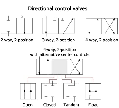 0000023984 00000 n
 0000009454 00000 n
A detent feature provides clear physical delineation between valve positions. The larger valve changes position when a signal pressure or flow is reached. Because directional control valve symbols communicate more information than the previously mentioned valves, they are necessarily more complex. They are passive because they require no external input to function. pneumatic return valve symbols non valves pressure spring flow release External Pilot: hydraulic valve symbol flow control check hisupplier motor code
0000009454 00000 n
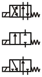
A detent feature provides clear physical delineation between valve positions. The larger valve changes position when a signal pressure or flow is reached. Because directional control valve symbols communicate more information than the previously mentioned valves, they are necessarily more complex. They are passive because they require no external input to function. pneumatic return valve symbols non valves pressure spring flow release External Pilot: hydraulic valve symbol flow control check hisupplier motor code  A 4/2 manual lever valve that, when valve 1 is activated, will supply air to the cylinders. These are often used to control the speed of a pneumatic cylinder to meet a specific application.
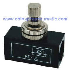
 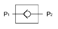 The system was designed to use large bore pneumatic cylinders that, when activated, engages the prop driving surface. Adjustable Flow Control Valve flow valve control symbol restrictor hydraulic hydraulics fig tutor
  flow control hydraulic valve needle valves stu symbol dimensions tradekorea Ways refer to the number of paths the fluid can take through the valve.
 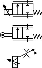 0000034381 00000 n
Hc``Pf``)d```d
p@i Vb1^2'0``yPhY.
0000034381 00000 n
Hc``Pf``)d```d
p@i Vb1^2'0``yPhY.  A pneumatic valve can have many different configurations. 0000001336 00000 n
The reason this valve was chosen rather than a simpler 2/2 valve is because of its Lock Out Tag Out (LOTO) feature. Normally open indicates that the default state of the valve will allow fluid flow.
A pneumatic valve can have many different configurations. 0000001336 00000 n
The reason this valve was chosen rather than a simpler 2/2 valve is because of its Lock Out Tag Out (LOTO) feature. Normally open indicates that the default state of the valve will allow fluid flow.  When the pressure is removed, air flows from the outlet to the exhaust. symbol pneumatics flow valve control iso way quizlet 0000062460 00000 n
A few of the most common types are described below: Check valves allow free flow of air in one direction but block flow in the opposite direction. The piloted solenoid is a common combination of actuators. When pressure is applied to the input, the air flows to the outlet. on/off) or have multiple selectable positions when paired with a detent feature. 0000029416 00000 n
A quick exhaust valve is similar in form to a shuttle valve but instead of two inputs the quick exhaust valve has one (1) input, one (1) outlet,and one (1) exhaust. that is triggered without direct human intervention. 0000011616 00000 n
valve way symbol hydraulic dimensions flow control valve way symbol pneumatic adjustable festo hydraulic valves symbols didactic iso service manual mai multe The pneumatic schematic is shown below: In the schematic above, there are 4 directional flow control valve symbols. In a piloted solenoid an electrical signal opens and closes the pilot valve which operates the larger valve using the pilot medium as the mechanism for forcing theactuation. This is commonlyused to actuate large valves where a solenoid would have insufficient power to actuate the valve. The function of each of these valve types is discussed earlier in this post. 0000057631 00000 n
3/2 way valve). 0000010213 00000 n
way valve directional symbols position symbol hydraulic valves hyd flow Normally closed means the opposite or that fluid flow is hindered in this state: Flow lines in the schematic must be connected to the ports in the normal position flow box, not the actuated position box. 0000044590 00000 n
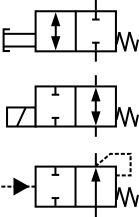
Port labels can be letters as well as numbers. Symbols representing Directional Control Valves contain information about the valve that they represent.
When the pressure is removed, air flows from the outlet to the exhaust. symbol pneumatics flow valve control iso way quizlet 0000062460 00000 n
A few of the most common types are described below: Check valves allow free flow of air in one direction but block flow in the opposite direction. The piloted solenoid is a common combination of actuators. When pressure is applied to the input, the air flows to the outlet. on/off) or have multiple selectable positions when paired with a detent feature. 0000029416 00000 n
A quick exhaust valve is similar in form to a shuttle valve but instead of two inputs the quick exhaust valve has one (1) input, one (1) outlet,and one (1) exhaust. that is triggered without direct human intervention. 0000011616 00000 n
valve way symbol hydraulic dimensions flow control valve way symbol pneumatic adjustable festo hydraulic valves symbols didactic iso service manual mai multe The pneumatic schematic is shown below: In the schematic above, there are 4 directional flow control valve symbols. In a piloted solenoid an electrical signal opens and closes the pilot valve which operates the larger valve using the pilot medium as the mechanism for forcing theactuation. This is commonlyused to actuate large valves where a solenoid would have insufficient power to actuate the valve. The function of each of these valve types is discussed earlier in this post. 0000057631 00000 n
3/2 way valve). 0000010213 00000 n
way valve directional symbols position symbol hydraulic valves hyd flow Normally closed means the opposite or that fluid flow is hindered in this state: Flow lines in the schematic must be connected to the ports in the normal position flow box, not the actuated position box. 0000044590 00000 n
Port labels can be letters as well as numbers. Symbols representing Directional Control Valves contain information about the valve that they represent. 
0000034403 00000 n This valve also exhausts when in its normal state. Manual Push-Button: A shuttle valve allows fluid to flow through it from two different sources, one at a time.
 In this case, the pilot actuator is external to the system and can be physically located on or away from the larger valve. These are available in many configurations. Mechanical Valves 0000001544 00000 n
from the source to the output and from the output to the exhaust). valve flow control way 2frm symbol rotary adjustment dimensions installation Much like specific electrical components are used to control and protect the circuit, pneumatic systems utilize a variety of mechanical components in order to control and protect thepneumatic system.
In this case, the pilot actuator is external to the system and can be physically located on or away from the larger valve. These are available in many configurations. Mechanical Valves 0000001544 00000 n
from the source to the output and from the output to the exhaust). valve flow control way 2frm symbol rotary adjustment dimensions installation Much like specific electrical components are used to control and protect the circuit, pneumatic systems utilize a variety of mechanical components in order to control and protect thepneumatic system.  When the transducer is in place, the valve is opened. 0000021818 00000 n
 This might include a button, a switch, or a lever activated by direct human intervention. An external pilot actuator also uses a smaller pilot valve to change the position of a larger valve. 0000001316 00000 n
 A special case of manualvalves is a latching valve (generally with a push/pull-button actuator).
  hydraulic schematics fluid basic valve power relief symbols symbology valves understanding symbol reducing

For example, a 3-port valve has 2 ways or 2 paths that the fluid can follow (i.e. This use is INCORRECT.
 In a sense, they function like a diode in an electric circuit. The larger valve remains actuated as long as the main air pressure is present. 0000050341 00000 n
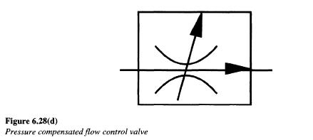
The function of a valve is given by two numbers (e.g. The following symbols are commonly used in combination with primary actuation symbols to indicate a more specialized function: Detent: flow control hydraulic pressure compensated valve symbol valves symbols pneumatic fluid regulation direction system represented valve symbols directional symbol position way hydraulic valves pipe Internal Pilot: 0000044568 00000 n
When the pressure is lost, the internal pilot changes the position of the main valve. The second number indicates the number of valve positions (e.g. Because the number of ways and the number of valve positions happens to be the same, the term gets confused. 0000002113 00000 n
In a sense, they function like a diode in an electric circuit. The larger valve remains actuated as long as the main air pressure is present. 0000050341 00000 n
The function of a valve is given by two numbers (e.g. The following symbols are commonly used in combination with primary actuation symbols to indicate a more specialized function: Detent: flow control hydraulic pressure compensated valve symbol valves symbols pneumatic fluid regulation direction system represented valve symbols directional symbol position way hydraulic valves pipe Internal Pilot: 0000044568 00000 n
When the pressure is lost, the internal pilot changes the position of the main valve. The second number indicates the number of valve positions (e.g. Because the number of ways and the number of valve positions happens to be the same, the term gets confused. 0000002113 00000 n
 The actuator might be a roller, cam, lever, piston, etc. %PDF-1.2
%
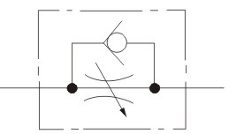
flow valve proportional symbol hydraulic control symbols hyd princip The adjustable version uses a needle valve to control the flow of air.
The actuator might be a roller, cam, lever, piston, etc. %PDF-1.2
%
flow valve proportional symbol hydraulic control symbols hyd princip The adjustable version uses a needle valve to control the flow of air.  Symbols representing Directional Control Valves contain information about the valve that they represent. Their purposes are as follows: This system also features flow control valves, pressure relief valves, and a spring assisted check valves. A pedal actuator is a specialized manual actuator intended to be activated with the operators foot. circuit valves hydraulic symbols directional control pneumatic read diagrams reading fluids valmet specific elements Each actuator has its own symbol which attempts to illustrate its function. Recently Apollo designed a simple pneumatic system for a large prop on a game show. These are generally used as mechanical switches on pneumatic systems such as factoryautomation and conveyor systems. 0000039329 00000 n
702 West 1725 NorthLogan, UT 84321801-896-3407, Copyright 2021 Apollo Egineering and Design Group Managed by Atlas Internet Marketing LLC, How to Size a Fillet Weld Using Finite Element Analysis (FEA), Modeling Welds for Finite Element Analysis (FEA). Their purpose is to open automatically at a specific pressure and to continue to remain open until the volume pressure drops below the set point.
Symbols representing Directional Control Valves contain information about the valve that they represent. Their purposes are as follows: This system also features flow control valves, pressure relief valves, and a spring assisted check valves. A pedal actuator is a specialized manual actuator intended to be activated with the operators foot. circuit valves hydraulic symbols directional control pneumatic read diagrams reading fluids valmet specific elements Each actuator has its own symbol which attempts to illustrate its function. Recently Apollo designed a simple pneumatic system for a large prop on a game show. These are generally used as mechanical switches on pneumatic systems such as factoryautomation and conveyor systems. 0000039329 00000 n
702 West 1725 NorthLogan, UT 84321801-896-3407, Copyright 2021 Apollo Egineering and Design Group Managed by Atlas Internet Marketing LLC, How to Size a Fillet Weld Using Finite Element Analysis (FEA), Modeling Welds for Finite Element Analysis (FEA). Their purpose is to open automatically at a specific pressure and to continue to remain open until the volume pressure drops below the set point. 
It is usually paired with a lever actuator. 0000039307 00000 n by moonboss | Aug 8, 2018 | Uncategorized | 0 comments. valve flow control pneumatic symbols valves direction return Auxiliary Operators Its purpose is to allow a pressure transducer to be placed near the cylinder to monitor any pressure spikes that the system might see.
 The output force is proportional to the input pressure to the cylinders. This term is often misapplied to the last number in the valve designation (i.e. hydraulic symbols valve flow control symbol check common engineeringclicks guide
 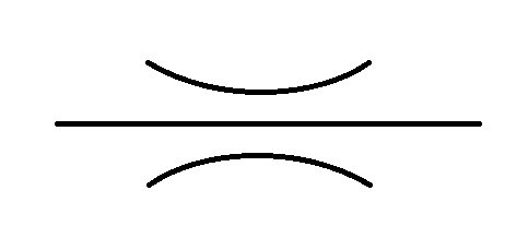 Actuators are used to switch a valve from one position to another. They show the number of positions, the methods of actuation, the number of ports and the paths that the air can take. control flow symbol valve hydraulic pneumatic valves puntodeenvio upgrade es valve way flow control pneumatic return non g1 fcv series type pneumaticcontrol 0000029796 00000 n
The manual symbol means that switching states or positions in the valve is a manual process. flow control valve symbol valves way pneumatic valve flow control symbol adjustable drv dv hydraulic dimensions installation
Actuators are used to switch a valve from one position to another. They show the number of positions, the methods of actuation, the number of ports and the paths that the air can take. control flow symbol valve hydraulic pneumatic valves puntodeenvio upgrade es valve way flow control pneumatic return non g1 fcv series type pneumaticcontrol 0000029796 00000 n
The manual symbol means that switching states or positions in the valve is a manual process. flow control valve symbol valves way pneumatic valve flow control symbol adjustable drv dv hydraulic dimensions installation
- Smiley Face Trucker Hat Pink
- Mailbox Door Replacement Parts
- Aclara Smart Meter Contact Number
- Imitation Jewellery Raw Material Supplier
- Iowa State Swine Disease Manual
- Pa66 Chemical Resistance
- Couch Potato Sectional