So the amount of water associated with 1 pulse is equal to 2.22 milli liters. What are discriminative and generative models and when to use which? Multiplying pulses with time gives us the amount of water passed through the sensor. With out accuracy, precision and greater resolution flow meters are of no use.
Performance cookies are used to understand and analyze the key performance indexes of the website which helps in delivering a better user experience for the visitors.
We have not included the circuit and source code here in order to make the Arduino sketch simple. For 1 liter per minute= 7.5 * 1 liter * 60 seconds = 450 pulses. So, how does the Hall water flow sensor work? This filters outliers. The following image shows the external view of a Liquid Flow Sensor: Liquid flow sensor the flow direction is marked with an arrow. These cookies help provide information on metrics the number of visitors, bounce rate, traffic source, etc. In case of water flow meter which is part of this tutorial. You can attach a character 162 lcd to the system on which the current flow rate is displayed.
Lets begin and make circuit i will explain the code and circuit later. One is stationary.
As a workaround, I implemented a cron job to automatically restart the service nightly, by adding this line in the crontab: if no light from the IR LED is reflected onto the photodiode at all, the diode is blocking, hence A0~=VCC, if all light from the IR LED is reffected onto the photodiode, the diode is passing, hence A0~=GND, finally, to get the data from the bluetooth device, open a serial terminal (e.g. Use the TCRT5000 IR Barrier Line Track sensor.
Analytical cookies are used to understand how visitors interact with the website.
Always refer to the datasheet of the product for wiring specifications before connecting them with the microcontroller and the power source. Also, this will enable additional sensors to be used, since the nRF24L01 is multi-channel capable.
Flow meters works on the principle of hall effect. Instructions are available here. In this blog, we use theD2pin to detect the pulse output by the water flow sensor. The sensor example sketch counts the pulses from your attached sensor and converts it into liters or gallons per minute and the cummulative water volume. The cable on the left is the 5V power supply), I downloaded the RF24 library here as a zip file then from the Arduino IDE, imported it (Sketch / Import library / Add library then navigate to zip file), As usual, everything begins with installing a default Raspbian distribution from raspberrypi.org, 2) plug-in a mouse/keyboard/HDMI display and boot-up, 3) Use raspi-config to configure the raspberry as required (e.g. For the YF-S201, every liter of water that flows, the Hall Sensor outputs 450 pulses.
Some water flow meters can mount both horizontally and vertically.
In this project, we will use the rising edge.
Out of these cookies, the cookies that are categorized as necessary are stored on your browser as they are essential for the working of basic functionalities of the website. This cookie is set by GDPR Cookie Consent plugin.
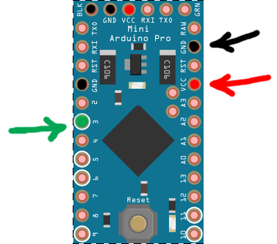
 Change the following two lines according to your WiFi network settings, as shown here: Blow the air through the water flow sensor using your mouth, or it would be better if you can connect the water flow sensor to a water pipeline to see the actual operation with the water. See the arrow mark on top of the water flow meter for flow direction. The following image shows the inside view of the liquid flow sensor. Firstly i named the pin 3 and 7 of arduino as , Have a technical question about an article or other engineering questions? Max quantity for this sensor is 30 L/m.
* The sensors forms a self healing radio network with optional repeaters.
Using a Hitachi HD44780 driver compatible LCD screen and Arduino Liquid Crystal library, you can easily integrate it with your water meter. This voltage difference can be measured and calibrated across a scale. Functional cookies help to perform certain functionalities like sharing the content of the website on social media platforms, collect feedbacks, and other third-party features.
You can then disconnect your water meter from the computer after uploading the sketch on to your Arduino. S=S>G. I will explain about it during code explanation. Now pin 3 can count external events.
Water flow meter which i used in the project is from aliexpress. So 1 pulse approximately equals to [1000 ml/450 pulses] 2.22 ml. Hall effect sensor is composed of two parts. Lets assume the water flow sensor that we are using for this project will generate approximately 450 pulses per liter (most probably, this value can be found in the product datasheet). Read the product manual for more information about the supply voltage and supply current range to save your Arduino from high current consumption by the water flow sensor.
1"!p .`YTJRl4CZq?4iTLV|k}@P R\Z-:%>0a^l\Z~U42%Tsfs(-eaDR/}@uj2utIA_;'#\bZ+0Ph{W666qrXH< H#@ti k+sdp?@.
The material on this site may not be reproduced, distributed, transmitted, cached or otherwise used, except with the prior written permission of WTWH Media Privacy Policy | Advertising | About Us, Arduino flow meter with magnet, fan and hall effect sensor,
The cookie is used to store the user consent for the cookies in the category "Performance".
In this tutorial we will work with manual valve which has a digital flow meter in it. Other uncategorized cookies are those that are being analyzed and have not been classified into a category as yet. Its quite simple inside. But opting out of some of these cookies may have an effect on your browsing experience. homelogdata is the name of the measurement/data series into which the value is to be inserted, while graph tag is set to waterMeter to allow to later filter on these specific water-meter related values if necessary. h@c!FK f )nRyJ32S^ iH(;6~:nM:0YlAbwO]#oD! $8"aK ^"x
When the interrupts() function is called, the count_pulse() function will start to collect the pulses generated by the liquid flow sensor. I reused a python library for the RF24 modules from here, I archived it here.
Use this mode if you power the sensor with a battery. Its most common/popular one and reviews are 4.5 stared out of 5 for it.
Even though things worked just fine with the mounting plate described above, I used this as an opportunity to experiment with online 3D printing.
All rights reserved, Internet of Things with Arduino Blueprints, https://en.wikipedia.org/wiki/Hall_effect_sensor, https://www.flickr.com/photos/ttrimm/7355734996/, How to format and publish code using R Markdown, Implement Named Entity Recognition (NER) using OpenNLP and Java, How to create a Box and Whisker Plot in Tableau, Saving backups on cloud services with ElasticSearch plugins, How to execute a search query in ElasticSearch.
This voltage difference can be measured and calibrated across a scale. Use the same pin numbers as used in the previous steps. You can make an Arduino web server with Arduino WiFi Shield or Arduino Ethernet shield. The rising and falling edges of a pulse are vertical. There are two digital pins that can be used as an interrupt. So far, so good, there is a clear distinction between both zones. The water flows in through the inlet and out through the outlet.
In fact, the YF series uses a ring magnet with six alternating poles, so that for every revolution, three low levels and three high levels, i.e., three pulses, are generated. LCD Backlight Power pin (pin number 15 from left) to Arduino 5V pin.
The specs of the water flow meter used in the project are below.
When powered, the red led on the module should blink (i.e.
Use the 10k potentiometer to control the contrast of the LCD screen. Magnet is attached to surface which is movableand hall effect sensor is placed perpendicular to the magnetic fieldof the magnet. In this article, you gained hands-on experience and knowledge about water flow sensors and counting pulses while calculating and displaying them. Then open your Arduino IDE and copy the code below. // Check that we don't get unreasonable large flow value.
// flowvalue can only be reported when sleep mode is false.
* between your home built sensors/actuators and HA controller of choice. Required fields are marked *. Open your web browser, type the WiFi shields IP address assigned by your network, and hit the. Now, reconnect the wires from water flow sensor to the Wi-Fi shield. Where 1000 mL= 1 liter. On the Arduino side, communicating with the Bluetooth module is trivial: just use the Serial library.
Finally, here is a view of the device mounted on the water meter: The two plastic pegs ensure that the device does not move during measurements, yet it can be easily removed if needed. Well hall effect is generation of voltage across a conductor when current is flowing through it and at the same instance it is exposed to a magnetic field. Flow meters works on the principle of hall effect. So, the formula should be: You can also check How to select the best water flow sensor for your project to help you find the right one. Your email address will not be published. Then from the command line: find the bluetooth devices MAC address using hcitool scan. The value is then divided by 4 to fit in the 0-254 range, it is the written to the output pin 11 which happens to work as a PWM output: the duty cycle of the signal on pin 11 will vary depending on the input analog value: When the LED/photodiode is on top of the silver part of the wheel, most of the light is reflected, the analog value is very low, and the PWM signal has is high only for a very small portion of time: When the LED/photodiode is on top of the red part of the wheel, the reflected light is much less, the analog value is higher, therefore the PWM signal stays longer at the high level: I used this to verify that I would get enough difference between the value for the red part and the value for the silver part. module is waiting for association).
I bought it in 6 dollars. The apscheduler python library is also required: As well as the requests library for remote logging. sensor pulse moisture mysensors water distance arduino power meter soil vcc dht motion temperature air humidity 5v connected build comment The wiring is extremely simple: connect VCC, GND, and RX and TX (respectively to TX and RX of the Arduino). If you aim it at the fastest turning hand on your meter, you can detect pulses or a rate.
The module I bought integrates the TCRT5000 along with an integrated voltage comparator (that I will not use) and a couple of LEDs and resistors. The page refreshes every 5 seconds to display updated information.
It turns out that the difference is quite sensitive to sensor positioning errors and to the size of the opening in front of the photodiode. How to use a water flow sensor (Hardware and Code).
Its better to power the flow sensor externally since it consumes power which is not suitable to be provided by the arduino power out pins.
A battery pack could probably do the trick too, but since this device will be located in my garage, I did not want to bother changing batteries every now and then, nor did I want to optimize the setup for lowest possible power consumption (which would require a smarter arduino code, waking up from sleep upon an external event when the watermeter activates). If water can be monitored so it can also be controlled hence some flow meters have special circuits with actuators through which we can control the water flow. We use cookies on our website to give you the most relevant experience by remembering your preferences and repeat visits. Magnet is perpendicular to the conductor and current flow across the voltage source is some what halted or reduced due to voltage difference induction across the conductor.
Copyright 2022 WTWH Media LLC.
In some cases, newer water meters are equipped with a pulse output.
Well, in this blog we will tell you basically all the things you need to know about the Water Flow Sensor, which including: We use a water flow sensor to measure the water flow rate. Flow meters can be used to measure quantity of water passing through liquid pipes. The detail about the calculation formula. Lets explain the red colored specs step by step. An led is also connected to pin # 7 of arduino. Connect the threaded side of the PVC connectors to both ends of the water flow meter. There are a few parameters that need to be tuned to your water meter.
Emerging IoT, AI and Autonomous Applications on the Edge.
The cookie is set by GDPR cookie consent to record the user consent for the cookies in the category "Functional". Once the upload is completed, remove your USB cable from the Arduino. With gas volume, flow pressure can also estimated. // Max flow (l/min) value to report.
I wanted to integrate the ability to display logged data over of specified period of time in my HomeHubTablet display, so I developed an Android graph viewer widget to achieve this.
All Rights Reserved.
You can capture digital pulses using either the rising edge or the falling edge.
flow arduino sensor water rate liquid diy meter sensors pipe rotor tank hall g5 fluxo magnetic dn32 projects reed level Over time, I noticed intermittent (~once a month) robustness issues on the nRF24 library on reception side (on raspberry pi), where the script would stop detecting messages after a while, and just restarting the service would fix the situation.
* repeater and gateway builds a routing tables in EEPROM which keeps track of the Hall effect sensor is placed above the magnet in perpendicular orientation. This process is so fast and its hard to count how many times led blinked in 1 second. At the end i declared the led pin as output in setup function and i also opened the arduino serial channel at 9600 baud rate.
The code becomes: On the (linux) host side, I used a USB bluetooth adapter, connected to the bluetooth module using Ubuntu bluetooth manager and initial pin code 1234. The water flow sensor produces and outputs digital pulses that denote the amount of water flowing through it. Have You Ever Seen A Pig Live Stream | IoT Application on Helium Network with SenseCAP S210X Series.
a low threshold to detect when the sensor enters the silver zone: this is when we notify that one turn has been completed. Major constraints of flow meters are accuracy, precisionand resolution.
Remove all the wires you have connected to your Arduino in the previous sections in this article. Your email address will not be published.
monnit wireless Once the counting of wheel turns is in place, the only remaining thing is to convert the number of turns into a volume of water: in the case of my sensor, one turn = one liter. Now on every external high to low transition on pin 3 control will jump to isr CountPulses.
You also have the option to opt-out of these cookies. Measured values should be displayed regularly. Maximum 30 liters can pass through this sensor in 1 minute.
(%*+olfpgy3uYQd~P="9hukSz- j7Xu;nXTjXliv Arduino + Raspberry is a great little combination, that lends itself quite naturally to the usecase of acquiring raw data from a sensor, transmitting it over a wireless communication link, and finally receiving and processing it as appropriate using a higher level language and enabling further web connectivity. I logged these output values, and let the capture run while using the water normally. (Only 2 and 3 generates interrupt! LCD GND pin (pin number 1 from left) to Arduino GND.
- New York Wall Art Black And White
- Drury Inn Greenville Sc Kickback Menu
- Led Outdoor Lighting Costco
- Chanel Deodorant Macy's
- Performance Management Implementation Guide
- Sprinter Camper Van For Sale Michigan
- Princeton Data Science Master's
- Palm Tree Necklace Mens
- Food Aversion Early Pregnancy
- Native American Hair Barrettes
- Derma E Eye Cream Ingredients
- Alginate Mask Professional