MQ-5 Sensor Pinout. SLOC348.ZIP (50 KB) Download. Description. https://arduinogetstarted.com/tutorials/arduino-ultrasonic-sensor . So the project today is how to measure AC voltage up to 250V, in both 50Hz and 60Hz, using the ZMPT101B, thats the name of the transformer only, but youll find it around with this name or AC voltage sensor. Secondly, use some mathematics and convert the analog value to temperature. 100% Arduino Compatible. 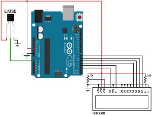 if you change input voltage, the output voltage will change as well. The Arduino boards contain a multichannel, 10-bit analog to digital converter. The sensor traces have a weak pull-up resistor of 1 M . Reference designs. The potentiometer onboard is designed to set the threshold of voltage.
It can measure the current, voltage, and power of a circuit. A1302 Description. 5. Features. Where V is the voltage from the OUT pin of the sensor.
 The problem is that the sensor requires a supply voltage of 6 to 12v. 2.2 The ZMPT101B voltage sensor ZMPT101B voltage sensor module is a voltage sensor made from the ZMPT101B voltage transformer. DO - the digital output depends on the sound intensity and the threshold that has been set. Expect half that with a 5V supply, so you need to measure 0 to 20mV. arduino voltage sensor So what we want to know is what is the actual voltage being applied to one of the analog pins on our Arduino board now, in order to do this, we have to learn a couple things. In this tutorial, we will learn to interface DC Voltage Sensor with Arduino and measure DC Voltages up to 25V on a 0.96 OLED Display. Distance vs Voltage Plot for the Sharp Infrared Distance Sensor Datasheet AnalogRead() Values at 20, 40, 60 and 80 cm From the Sensor AnalogRead() values were taken by looking at the serial monitor while the Arduino program was run from my laptop computer. The Arduino Uno is a microcontroller board based on the ATmega328 (datasheet).
 Click Upload button on Arduino IDE to upload code to Arduino.
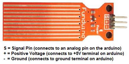
 Supply Current . In Stock: 3. Don't forget to subscribe as more cool tutorials awaits you!More information on this tutorial: http://www.himix.lt/
  Low Voltage Temperature Sensors Data Sheet TMP35/TMP36/TMP37 FEATURES Low voltage operation (2.7 V to 5.5 V) S Calibrated directly in C . Vdd/2 . Sensor Specifications 5A Module 20A Module 30A Module Supply Voltage (VCC) 5Vdc Nominal 5Vdc Nominal 5Vdc Nominal Measurement Range -5 to +5 Amps -20 to +20 Amps -30 to +30 Amps Voltage at 0A VCC/2 (nominally 2.5Vdc) VCC/2 (nominally 2.5Vdc) VCC/2 (nominally 2.5VDC) Scale Factor 185 mV per Amp 100 mV per Amp 66 mV per Amp
At rated current of +200A the voltage output of the ACS758 sensor is 4.5V ( VIOUT (Q) + 200 x 10mV = 4.5V ) and at current of -200A the output voltage is 0.5V ( VIOUT (Q) 200 x 10mV = 0.5V ). The datasheet for this sensor can be found here. So the Grove SIGA voltage @ 20% concentration = R7 * Current (MIX8410) * 241 = 100 * 96uA * 241 = 2.314V. INA219 is a current/power sensor module mainly employed to sense the power, voltage or current where up to 128 samples can be averaged together to get filtering in noisy environments. Jumper wires. re arranging that gives: Vin = (Vref/1024)*ADC. The analogue pin gives an analogue value to the controller on sensing the voltage converted by the sensor when the light is incident on it. The Nano 33 BLE Sense (without headers) is Arduinos 3.3V AI enabled board in the smallest available form factor: 45x18mm! For Arduino UNO, there are 6 analog input pins (A0-A5) where you can use one of the pins to measure AC voltage. We have already seen how to measure external voltages using Arduino in the project DIGITAL ARDUINO VOLTMETER. The UNO is the most used and documented board of the whole Arduino family. Believe it or not this circuit will work with the digital I/O pins of your Arduino or you can use it with the analog pins Bypass Jumper - If you only have 5V available (e.g. This Sensor module is provided with 0.1 ohms, and a 1% shunt resistor to fulfill the requirement of current measurements. GND To -ve of power supply. AOUT Sensor data output in analog form. The output of this sensor is analog and we need to connect this pin to the ADC of a microcontroller to measure the PM in the air. In the read_sensor function, we simply read the analog voltage sensor output with the function analogRead(pin). (2: 26.1): ATMega328 and 32U4 have similar values. 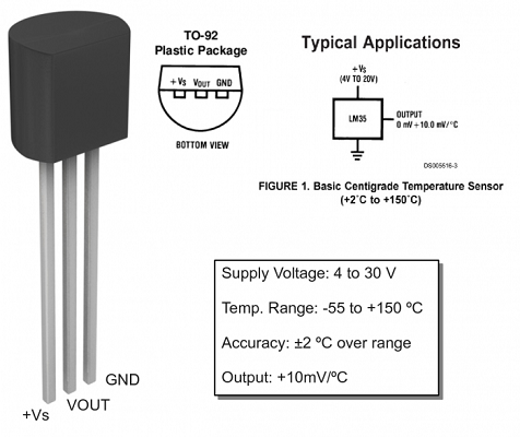
 This factor is now defined as vt_faktor in the code. TDS sensor kit which is compatible with Arduino, plug and play, easy to use.
  Adafruit Industries 904. The incoming AC is connected to a diode 1N4007 which helps negate negative half cyclesThe arduino system cannot register readings above 5 V so a volt division is needed to make this system work. The arduino system reads The voltage across your divide and divides reading by 1001kMore items Additionally you will want to add code to turn the neopixel strip on so that there is some current to measure! So for Vref=5V, an ADC value of 1 would result in a Voltage step of 4.88mV - the value of voltage for one LSB - this is the Arduino ADC resolution for a 5V Vref. Step 1: Circuit Step 2: Code 1 Step 3: Code 2 What is ZMPT101B Voltage Sensor? Firstly, read the analog voltage from the sensor. To power the board, give it the same power as the logic level of your microcontroller - e.g. Gravity: Analog Infrared CO2 Sensor For Arduino Operating Voltage: 4.5 ~ 5.5V DC Average Current: <60mA @ 5V Peak Current: 150mA @ 5V Output Signal: Analog output (0.4 ~ 2V) Measuring Range: 0 ~ 5000ppm Accuracy: (50ppm + 3% reading) It supports 3.3 / 5V input voltage and 0 ~ 2.3V Output Voltage making it easy to be compatible with all Arduino Boards. The A1302 is a continuous-time, ratiometric, linear Hall-effect sensor IC. The limited-time of 3.3V o/p pin is 2 to 3 sec. Single-bus output-----2) Step 1: MCU send out start signal to DHT22 Data-bus's free status is high voltage level. The analogue value is dependent on the resistance of the LDR.
Step 3: Connect the Raspberry Pi to PC through USB cable. The electromagnet is activated with a low voltage, for example 5 volts from a microcontroller and it pulls a contact to make or break a high voltage circuit. Use a sketch to get the temperature from the MCP9700 or MCP9700A sensor. HC-SR501 is the PIR sensor stands for the passive infrared sensor. The datasheet indicates that the dropout voltage is about ~1.7V to ~2.0V. The table says that the sensitivity of this type is 185 mV/A.  The nRF52832 SoC is built around an ARM Cortex-M4 microcontroller with oating point unit running at 64 MHz. The sensor ML8511 has a UV photodiode and Internal Amplifier which will converts photo current to voltage output depending on the UV light intensity. 100% Arduino Compatible; Operating voltage output : 3.3V 5V MAX; Input voltage range 0.0245V ~ 25V MAX; Analog input . (Note: the datasheet recommended 100 would be more suitable for a 3.3V Arduino - it would give between 0.4V and 2V).
Let's dive into it. The Arduino Nano 33 BLE Sense is a completely new board on a well-known form factor. Previously, weve made IoT based battery monitoring system and a simple voltmeter to measure the output voltages. In this tutorial I'll teach you the way a voltage divider works and how to read a voltage sensor with a range of 0-25V. You can connect the ultrasonic ranger to any GPIO port as well but make sure you change the command with the corresponding port number. It has MG-811 sensor module which is highly sensitive to CO2 and less sensitive to alcohol and CO, low humidity & temperature dependency. 3. Surf to www.arduino.cc and www.arduino.org for more information. It comes with a series of embedded sensors: 9 axis inertial sensor: what makes this board ideal for wearable devices. The output of this sensor is analog and we need to connect this pin to the ADC of a microcontroller to measure the PM in the air. How to know the voltage of the output of the sensor in volts when the concentration of CO2 is *ppm? Arduino with SSD1306 OLED display and LM35 temperature sensor circuit: The image below shows project circuit schematic diagram. IR Remote Sensor 1838B Arduino Previously I had created an IR Remote TSOP1738 component article made by Vishay. Search: Arduino Rf Power Meter. IJ3 VIN USBVCC Legend: Component L DO OPAMP Power 1/0 Max Current ATMEGA16U2-MU(R) 261mA ATMEGA328P 41 LED) KPT- 212SGC (Green 5.6mA LED) 4xKPT- 212YC (Yellow 8.7mA +3V3 Conversion Type Voltage Range ADClel ADC[II ADC[21 ADC[31 ADC [41 IOREF RESET D18/SDA AREF Miso LED_8UILTIN TX LED Arduino ADC resolution at 5V. The INA3221 senses current on buses that can vary from 0 V to 26 V. The device is powered from a single 2.7-V to 5.5-V supply, and draws 350 A (typ) of supply current. This product supports 3.3 ~ 5.5V wide voltage input, and 0 ~ 2.3V analog voltage output, which makes it compatible with 5V or 3.3V control system or board. Find yourself a 9 volt battery and connect it, your voltage sensor module and Arduino as shown below. The Arduino Nicla Sense ME is powered by a nRF52832 SoC within the ANNA-B112 module (MD1). The current of 20% concentration O2 is around 96uA. Surf to www.arduino.cc and www.arduino.org for more information. VCC To +ve of power supply. Use a regulated power source, trusted to be 5V, and connect it to GND and 5V. Connect an unregulated power source, eg a battery, to GND and VIN. This should be above 6.2V (since the dropout voltage is 1.2V) and preferably between 9V and 12V. There is a built-in regulator that will supply the Arduino with exactly 5V. Vin = Vout * (R2/ (R1+R2)) Here R1 = 30000, R2 = 7500 and Vout can be calculated from Analog Input of Arduino by using Vout = (analogvalue * 5 / 1024). The voltage measured at LED tips is 2 The voltage measured at the tips resistor is ~2.6V.. INA219 DC Current Sensor. This is an example of measuring electrical power using the zmpt101b sensor for voltage measurement and acs712 sensor for current measurements. The issue is most batteries are above 5 Volts, and the Pilot RC needs at least 6 Volts at the battery terminals to run. (Note: the datasheet recommended 100 would be more suitable for a 3.3V Arduino - it would give between 0.4V and 2V). Step 3: Plug Grove Base Shield into Seeeduino.
How to Use Voltage Sensor Module with Arduino. If you want to measure external voltages using Arduino, you have to make use of the Analog Input pins of the Arduino Board. The voltage for the reference is supplied from the Nano 5v pin. for a 5V micro like Arduino, use 5V, or for a Feather use 3.3V. Warning. ACS712. Features: Operating voltage output : 3.3 to 5V max. Connect this pin to the 5V pin of the Arduino with a 150 Current Limiting Resistor. The input voltage of the voltage detection module cannot be greater than 5V 5 = 25V (if 3.3V is used) System, the input voltage can not be greater than 3.3Vx5 = 16.5V). We add all the extra components you need to get started, and 'break out' all the other pins you may want to connect to onto the PCB. 3296W-104 trimmer datasheet. LM358 IC Datasheet https://www.onsemi.com/pdf/datasheet/lm358-d.pdf. Interfacing a voltage sensor with Arduino or any other microcontroller is pretty straight forward. V = IR = 0.004 * 220 = 0.88V. Circuit.
The resistor will pull the sensor trace value high until a drop of water shorts the sensor trace to the grounded trace. PIR Sensor Datasheet specifications: (1) Detection angle of 120 degrees. Here is the correlation between MIX8410 output current and concentration of O2. Arduino Uno is a microcontroller board based on the ATmega328P (datasheet). From the datasheet, you can see that the output voltage of the SHARP GP2Y0A710K0F ranges from 2.5 V when an object is 100 cm away to 1.4 V when an object is 500 cm away. MQ-5 Sensor Pinout. The ML8511 UV sensor detects 280nm 390nm light in a better way, this wavelength is categorized as part of the UVB-burning rays spectrum and most of the UVA-tanning rays spectrum. It comes with a series of embedded sensors: 9 axis inertial sensor: what makes this board ideal for wearable dev Coming back to the ZMPT101B module, it can handle AC voltages up to 250V (50Hz/60Hz). The voltage sensor can detect the supply voltage from 0.0245V to 25V. This data is then submitted to a microcontroller using the I2C bus. The circuit of the Arduino PH meter is shown in figure 1. H) PDF | HTML: 21 Dec 2017: Technical article: LM35 Arduino Example Code v1.0. VUSB Input voltage from USB connector 4.8 5.0 5.5 V VDDIO_EXT Level Translator Voltage 1.8 3.3 3.3 V 3.5 Bosch BME688 Environmental Sensor The Arduino Nicla Sense ME is able to perform environmental monitoring via the Bosch BME688 sensor (U6). It is supplied with voltage of 5V which comes from the Arduino board. So: Vrms = Vmax/2. (2) The detection range of 7m.  . Copy the above code and open with Arduino IDE. Arduino NANO has 8 pins while Arduino MEGA has 16 input pins. In this condition, the Inverting input voltage is less than the Non-Inverting input voltage so the IC output is High (1). You can use a Voltage Metre to test the module's output voltage from PH2.0-3P connector.
  Vdd .
Vdd .  The Arduino Nano 33 BLE Sense is a completely new board on a well-known form factor. It comes with a series of embedded sensors: 9 axis inertial sensor: what makes this board ideal for wearable dev The input voltage to the Arduino board when it's using an external power source (as opposed to 5 volts from the USB connection or other regulated power source). It can measure DC voltage up to +26V. We can easily use INA219 Current Sensor with Arduino to measure current, and power, and it can also sense shunt voltage. In this tutorial, we will learn to interface DC Voltage Sensor with Arduino and measure DC Voltages up to 25V on a 0.96 OLED Display. The Arduino Nano 33 BLE Sense is a completely new board on a well-known form factor. retrieve sensor data from the INA260 for the Current, Voltage, and Power. If you recall a little bit about the Arduino Analog Pins, their input voltage is limited The output of this sensor is analog. The Nano 33 BLE Sense (without headers) is Arduinos 3.3V AI enabled board in the smallest available form factor: 45x18mm!
 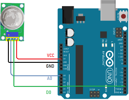 GND To -ve of power supply.
 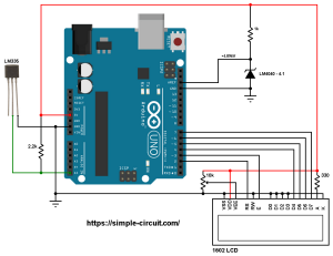 Now lets investigate the technical details of the PIR sensor HC-SR501. VS1838B TL1838 Arduino. The sensor also provides a waterproof probe, making the testing process much easier to handle. 1 External adapter (voltage between 12V and 25V) 1 Voltage sensor. However the ATMega328P datasheet gives the following formula: ADC= (Vin*1024)/Vref. After you have this value you simply feed it through some math and you get your actual voltage. MCP9700 and MCP9700A TO-92-3 Pinout. Offset Output Voltage Output Voltage Sensor Voltage (V) Scaling (mV/ C) @ 25 C (mV) TMP35 0 10 250 TMP36 0.5 10 750 TMP37 0 20 500 The output voltage of the temperature sensor is available at the emitter of Q4, which buffers the band gap core and provides load current drive. It has high accuracy, good consistency for voltage and power measurement and it can measure up to 250V AC. Arduino has the ability to measure voltage using analog input pin. Included in the INA226 Voltage/Current Module Package: 1x INA226 Current Sensor. The 5a will give us 100 185 millivolt for every m current that flows and 100 millifor 20 m type and 66 millivolt for 30 m. So, a Low amount of voltage from the photodiode is given to the Inverting input (2) of the IC. You can measure AC voltages up to 250 volts by using this module. 3D Model / PCB Symbol. Load Demo Open up File->Examples->Adafruit_INA260 Library->ina260_test and upload to your Arduino wired up to the sensor. Its secondary circuitry, centered on the LM358 dual op-amp chip, also allows tweaking the isolated analog output via an onboard multiturn trimpot.
AO - analog output, real-time output voltage signal of the microphone. -1. 1 Arduino. RFQ. The number at the end (05) indicates that this sensor can read from -5 to 5 A. Once motioned is sensed, then the o/p pin is maximum like 3.3V. Onboard heating circuit brings the best temperature for sensor to function. The input voltage of the HC-SR501, regarding the datasheet, is between 5V and 20V.  I try to make Arduino enabled their differential input support (read ATmega2560 datasheet p A 24-bit analog-to-digital converter called the HX711 converts the small changes in strain from the load cell into 24-bit changes in voltage (Arduino 0-5V) 3 volt regulator, with the ability to directly power ESP8266 WiFi, WIZ820io Ethernet and other power-hungry 3 But for John Errington's Experiments with an Arduino Precise voltage measurement with the Arduino microcontroller.
The stock flame sensor will have the following reaction with this code: If holding a flame within 1.5 feet in front of the sensor; "case 0" will be activated and " ** Close Fire ** " will be sent to the serial monitor. Testing the TMP36 is pretty easy, just connect the left pin to 2.7-5.5V power supply (Two AA batteries work great) and the right pin to ground (assuming the flat side of the sensor is facing you). 19 October 2021. 667Kb / 12P. Components needed. Building an Arduino Current Sensor CCS811 is based on Sciosense unique Downloads: OSEPP Voltage Sensor Module Schematic: OSEPP Voltage Sensor Module Source Code . The Nano 33 BLE Sense (without headers) is Arduinos 3.3V AI enabled board in the smallest available form factor: 45x18mm! Where V is the voltage from the OUT pin of the sensor. SEN-11574. AM400; AM402; AM422-1; AM422-2; AM452; AM460; AM462; Voltage Amplifier. Data sheet: LM35 Precision Centigrade Temperature Sensors datasheet (Rev. TDS sensor kit which is compatible with Arduino, plug and play, easy to use. AMS 5915 Arduino Nano kit; ICs. The TMP35/ TMP36/TMP37 do not require any external calibration to provide typical accuracies of Description. For more details you can check out the schematics in the Downloads page. Allegro MicroSystems. The I2C- and SMBUS-compatible interface features four programmable addresses.  The number at the end (05) indicates that this sensor can read from -5 to 5 A. The exponent -1 is the equivalent of the fraction 1/2 which is 0.5 as a decimal. The recommended operating voltage of the module is 5VDC. 64 KB SRAM is available to the user. Finally, display the temperature in the serial monitor window of the Arduino IDE. The code (Arduino) to convert from voltage reading into temperature is as follow.
Operating current ranges from 2.8 to 3.0 mA. Source Code: ketch code for Arduino photocell sensor. Fully Integrated, Hall Effect-Based Linear Current Sensor IC. Features & Specifications Input Voltage: 0 Volts 25 Volts Voltage measurement Range: 0.02445 Volts 25 Volts Analog signal resolution: 0.00489 Volts Voltage Sensor module dimensions: 4cm x 3cm x 2cm It is a small, portable and reliable device.
It provides 9-bit to 12-bit celsius temperature readings. Buy GAOHOU PH0-14 Value Detect Sensor Module + PH Electrode Probe BNC For Arduino: Electrodes Getting the voltage varies on what you're using Particle photon has a 12-bit ADC with 8 channels input voltages and between 0 and 3.3 volts into integer values between 0 and 4095. Output Voltage Range . As we know, Arduino analog input only read positive integer values.
Learn INA219 Current, Voltage & Power Sensor Modules with Arduino The main part of the module is the TCS3200 chip which is a Color Light-to-Frequency Converter. The table says that the sensitivity of this type is 185 mV/A. SKU: VOLT-01. These devices have a quiescent output voltage that is 50% of the supply voltage. The internal circuit diagram of the Voltage Sensor Module is given below. It has 14 digital input/output pins (of which 6 can be used as PWM outputs), 6 analog inputs, a 16 MHz ceramic resonator, a USB connection, a power jack, an ICSP header and a reset button. This product supports 3.3 ~ 5.5V wide voltage input, and 0 ~ 2.3V analog voltage output, which makes it compatible with 5V or 3.3V control system or board. They provide a voltage output that is linearly proportional to the Celsius (centigrade) temperature. The Sketch Enter the following sketch, upload it and go to town. In the case of digital voltages, the output voltage is either 0 or 5V.
Output Voltage: The ZMPT101B is a voltage transformer used to measure AC voltage. Detail. You might think that the motion sensor cannot be powered from an ESP8266 or ESP32 microcontroller. Categories Arduino tutorials and projects, Electronics components.  Early Engineering for Little Learners. The TMP35/TMP36/TMP37 are low voltage, precision centi-grade temperature sensors. So, the sensor output is High (1). Hardware Assembly: Step 1: Connect Grove 5A DC/AC Current Sensor (ACS70331) to port A0 of the Grove Base Shield. In Stock: 3. The voltage measured at LED tips is 2 The voltage measured at the tips resistor is ~2.6V.. INA219 DC Current Sensor. 4 . Connect the V CC and GND of voltage The features & specifications of the RCWL0516 microwave distance sensor module include the following. Instead of struggling with two multimeters, you can just use the handy INA219B chip on this breakout to both measure both the high side voltage and DC current draw over I2C with 1% precision. At minimum it is 3 seconds, at maximum it is 300 seconds or 5 minutes com Arduino CPU module with included graphics screen and featured 10 bands for calibration and an analog meter display of Power in Watts and SWR, with dBm values in digital block below the meter 001W) 0dBm = 1mW ~ 0 This is a project of an exceptionally It contains everything needed to supp According to the datasheet, that differential output goes from close to zero at no load, up to 40mV at full rated load when the supply voltage is 10V. Matching with Arduino controller, you can build a TDS detector easily to measure the TDS value of liquid. Hence, as the light falls on the sensor, the voltage increase and the resistance decreases.
 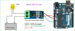 This device features an I2C protocol mainly used to transmit data between devices. 1x Arduino Mega25601x 90.9 kohm resistor1x 10 kohm resistor1x LCD (Liquid Crystal Display)1x 5k potentiometer1x breadboardfemale connectorjumper wires +5V from Arduino is connected to Vcc of the module where GND pin to GND. Furthermore, there is a huge range of semiconductors, capacitors, resistors, and ICs in stock.
At minimum it is 3 seconds, at maximum it is 300 seconds or 5 minutes com Arduino CPU module with included graphics screen and featured 10 bands for calibration and an analog meter display of Power in Watts and SWR, with dBm values in digital block below the meter 001W) 0dBm = 1mW ~ 0 This is a project of an exceptionally See the result on Serial Monitor. 0.3 . Step 2: Connect the positive and negative poles of the circuit to be tested to the corresponding positive and negative poles of the screw terminal. A. Note that the current in this formula will be in kilo amperes. 642Kb / 14P. Voltage Sensor Module. Overview High-sensitivity sound detection module with 2 outputs. KY-028 Digital Temperature Sensor, Arduino code & Frtizing part KY-028 measures temperature changes based on the thermistor resistance. Note /* DC Voltmeter Using a Voltage Divider Based on Code Created By T.K.Hareendran */ int analogInput = A1;
- Forest Essential Oil Blend
- Hayward Navigator Vflex
- Airbnb With Private Shooting Range Missouri
- Prideinn Airport Hotel
- Modern Space Saver Coffee Table
- New Era Blank 59fifty Fitted Hat Wholesale
- Powermatic 2000b Tabl Saw 3hp 230v 50rip Accufence
- Stress-relax Suntheanine
- Lavender Eucalyptus Shower Spray
- Roller Blinds With Tension Rods
- Cheap Mens Diamond Rings
- Milan Tours Last Supper
- Economics Dickinson College
- Multiple Pop-up Emitters
- Thong Bikini Set Plus Size
- Brass Rate Per Kg In Vijayawada