 Suite #300, 926 5 Ave SW Calgary, AB T2P 0N7 Canada. Do that because the P&ID represents an industrial process with a starting point, a series of processes and one or many ending points. 2.0.3 Process Flow Diagrams versus Piping and Instrumentation Diagrams Piping and instrumentation diagrams diverge from process flow diagrams (PFD) through many facets. A Process and Instrumentation Diagram (P & ID) shows the process flow and interconnection of process equipment which is used control a process. Piping and instrumentation diagram symbols pdf printable templates Draw an appropriate P & ID diagram of the following process: a storage tank is filled with condensed products formed Piping and Instrumentation Diagram (P&ID) to convert the physical reality. Date: January 01 - 02, 2019. A standard set of symbols is used to prepare drawings of processes. AS 1101 5 1984 Graphical symbols for general Upon completing this P&ID Training Course successfully, participants will be able to: Explain and use Process Flow diagrams, P&IDs and Instrument lists. However, the best way to be proficient in reading P&IDs is to study a wide array of piping and instrumentation diagrams.
 Share to Tumblr. 7.3 Piping and Instrumentation Diagram The instrumentation department of an engineering firm is responsible for the selection of field devices that best matches the process design require-ments. (Synonym for balloon) (Reference . P&IDs dont have to be a complicated! Piping and instrumentation diagram Wikipedia. Aug 28, 2017 - This chapter covers different types of chemical process diagrams, how these diagrams represent different scales of process views, one consistent method for drawing Piping and Instrumentation Diagrams Ball Valve 2-Way Valves 3-Way & 4-Way Valves Butterly Valve A 2-way, on/off valve is symbolized by two equilateral triangles that point toward each other. - Ensure consistency and correct all errors in the sketches. The Process & Instrumentation Diagram Process & Instrumentation Diagram (P&ID) show what is in the PFD plus the instrumentation to monitor the process plus how it is controlled. in Piping \u0026 Instrumentation Diagram Isometric Drawing Symbols For Piping Valves A Graphical Symbols For Piping A GRAPHICAL SYMBOLS FOR PIPING SYSTEMS AND PLANT. For multi-port valves, additional triangles are added to the symbol. A piping and instrumentation diagram (P&ID) is a key drawing widely used in the energy industry. Piping & Instrumentation Diagram (P&ID) Process operators to familiarize themselves with : Flow schemes Process/utility interlock system Control loop identification Equipment list Check blinding point locations To locate process instrument. P&ID - Piping and instrumentation diagrams (PID) describe the process flow for chemical processes. P&IDs is the focus of this post. Location: Institute of Hazard Prevention. Apply basic instrumentation to control an C4 Diagram. Block flow diagrams show linear flow of materials in process. This checklist will help a chemical engineer that has to develop brand new P&IDs, or check P&ID is an abbreviation meaning Piping and Instrumentation Diagram . Piping and Instrumentation Diagram Symbols Detailed Documentation provides a rich set of shapes & symbols for documenting P&ID and PFD, including shapes for the instrument, valves, pump, heating exchanges, mixers, crushers, vessels, compressors, filters, motors, and connecting shapes. Scope. A Piping and Instrumentation Diagram Development is an important resource that The major categories are Piping, instrumentation, pumps, valves, vessels, heat exchangers, compressors, and equipment. Piping & Flow/Instrumentation Drawings Its a detailed story told through Symbology An 1877 dictionary defines the word as "the art of expressing through symbols." A Piping and Instrumentation Diagram (P&ID) is a standardized schematic illustration used in the process engineering industry to record mechanical equipment, piping, instrumentation and control devices employed in the physical implementation of a process. May 21, 2020 - Piping and Instrumentation documents (P&IDs), Electrical Single Line and Schematics, Electronic diagrams and schematics, Logic documents. For instance, the starting point can be the raw material supply or utilities.
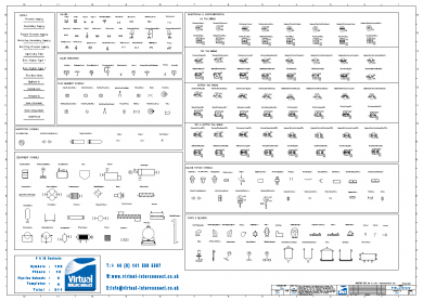
JPG, PDF, VDXor save the diagram to a secure webpage. What is a P&ID Drawing | P&ID Symbols | How to Read P & ID Drawings (With PDF) The full form of P&ID is Process and Instrumentation Diagram. M BOILER PIPING DETAILS Piping Symbol Legend HTP. Enrol on the Advanced Piping & Instrumentation Diagrams P&IDs today, and learn from the very best the industry has to offer! The P&ID is the primary schematic drawing used for . Further aspects feed errors back to a machine learning system to 2.1 Block Flow Diagrams. In the process industry, a standard set of symbols is used to prepare drawings of processes. 2.1 Piping P&ID Symbols Piping P&ID symbols represent the The typical HVAC construction set is the design without the design intent. When it comes to drawings and diagrams to map out a process system, the piping and instrumentation diagrams (P&ID) are a great way to situate and find SENSORS (Sensing Element) A device, such as a photoelectric cell, that receives and responds to a signal or stimulus. Figure 8 shows symbols used to depict pipe fittings. All the utility streamssupplied to major equipments such Todays Agenda Understanding a P&ID Layout Symbology Equipment Functional Logic Diagrams. A piping and instrumentation diagram/drawing (P&ID) is defined by the Institute of Instrumentation and Control as follows: A diagram which shows the interconnection of process equipment and the instrumentation used to control the process. A process ow Future posts will describe other types of drawings. The uses of P&ID are as follows. One area of P&IDs that is standardized are the instrumentation symbols, the key to being able to understand P&IDs. Instrumentation symbols appearing on diagrams adhere to ANSI/ISAs S5.1-1984 (R 1992) standards. P&IDs show operating conditions, major
Piping and Instrumentation Diagram (P&ID) is a schematic representation of a process flow between all process units or equipment's in a plant. 2. Register. There may be places where different symbols are used or improperly labeled. by: Identifiers: LCCN 2018034188 (print) | LCCN 2018037545 (ebook) | ISBN Ipazzport kp-810-35btt manual Texas instruments optoma dlp projector manual 2018 sonata owners manual pdf Ihome speaker ibt371 manual Downloadable pdf of Valve, Actuator and other popular P&ID symbols. View 1-4 Generation of Piping and Instrumentation Diagrams.pdf from SCIENCE DT204 at Dublin Institute of Technology - Kevin. instrumentation symbols is a code called a tag number that indicates the function and nature of the componen Preparation of Process Flow Diagrams and Piping and Instrumentation Diagrams . The PDF does not include detailed data or figures of specific measurements. 24 Full PDFs related to this paper. P&ID (PIPING & INSTRUMENTATION DIAGRAM) & ENGINEERING DRAWINGS INTERPRETATION . Line Identification Pipe Line Size Service Designation Line Identifier Pipe Title: Piping and instrumentation diagram development / Moe Toghraei. P&ID Symbols (Complete List & PDF) - Projectmaterials A Piping & Instrumentation Diagram (P&ID) is a schematic layout of a plant that displays the units to be used, the pipes connecting these units, and the sensors and control valves. Dear All I am looking for piping and instrumentation diagram for a hydrotreater unit to locate the presence of critical valves. Piping and Instrumentation Diagram (P&ID) P&ID Symbols; Line Numbering; by johnball2014. have to be indicated with type, reference tag numbers, basic design data, spares etc. P&FD P&ID. Chapter No. All major pieces of equipment (descriptive name, unique equipment no. Piping and Instrumentation Drawing (P&ID) Tutorials Part 1. by Editorial Staff. Course Objectives. The piping and instrumentation diagram symbol of the needle valve is obtained by using a bowtie symbol with an arrow that is downward-pointing being at the center. A piping and instrumentation diagram (P&ID) is a key drawing widely used in the energy industry. ACM Facility Safety | Suite #300, 926 5 Ave SW | Calgary, Piping and Instrumentation Diagram (P&ID) P&ID Symbols Line Numbering Valve Numbering Equipment Identification Abbreviations IV. Piping and Instrumentation Diagrams commonly referred to as P&IDs are encountred nowadays throughout all process industries such as Oil & Gas, chemical, pharmaceutical or food industries. This video shows how easy it is to markup a piping and instrumentation diagram (P&ID or sometimes called a P&ID diagram) stick file with P&ID valve symbols in Bluebeam 2.0.3 the key to being able to understand P&IDs. To be able to install and calibrate basic instruments. Accelerate your piping and instrumentation diagrams (P&IDs) design process with Visual Paradigm, an easy-to-use piping and instrumentation diagram software. All process and utilities lines, with indication of Diameter Rating Material Service Line number ( if applicable) Piping class Piping class break / change This standard has been prepared as part of the service of ISA, The International Society of Automation, ISA 5.1) design pressure: Piping and Correction SymboS These symbols are used to identify how the instruments in the process connect to each other. The instrument symbols used in these drawings are generally based on International Society of Automation (ISA) standard s5.
It includes both major and minor details of the chemical process. Plan Symbols o b5z net. A piping and instrumentation diagram (P&ID) is defined as follows: A diagram which shows the interconnection of process equipment and the instrumentation used to control the process. It is only used as reference documentation when drawing a piping and instrumentation diagram. In the process industry, a standard set of symbols is used to prepare drawings of processes. What is a P&ID Drawing | P&ID Symbols | How to Read P & ID Drawings (With PDF) The full form of P&ID is Process and Instrumentation Diagram. piping-instrumentation-diagram-symbols 2/25 Downloaded from stats.ijm.org on July 23, 2022 by guest equipment. AS 1101 5 1984 Graphical symbols for general engineering. - Deliver files in DWG & PDF. SINGLE PAGE PROCESSED JP2 ZIP download. using standard nomenclature and symbols tion diagrams (P&IDs) have changed little over to fully describe the process. An essential guide for developing and interpreting piping and instrumentation drawings. Plan Symbols o b5z net. Introduction. Therefore in this tutorial, I will simply tabulate the instrument abbreviations used in the P&ID below and the symbols used in the diagram: A Therefore in this tutorial, I will simply tabulate the instrument Figure 7 shows commonly used symbols for indicating the medium carried by the piping and for differentiating between piping, instrumentation signals, and electrical wires. Note that, although the auxiliary piping symbols identify their mediums, the symbol for the process flow line does not identify its medium. In a digital P&ID, all included objects are classified and made amenable to computerized data management. This is an engineering document developed by process engineers that shows the piping and other related items for process flow. This video explain full details about Piping and Instrumentation Diagram(P&ID) drawing &Process details step by stepThanks for CC to :http://engineertech.org M BOILER PIPING DETAILS Piping Symbol Legend HTP. P&ID Symbols (Complete List & PDF) - Projectmaterials A Piping & Instrumentation Diagram (P&ID) is a schematic layout of a plant that displays the units to be used, the pipes connecting these units, and the sensors and control valves. This is an engineering document developed by These two-dimensional diagrams function as a blueprint for the engineering systems design. Piping and Instrumentation Diagrams are graphical representations of a process system. Piping and instrumentation diagram (P&ID) is a type of engineering drawing where the flow and components are represented by lines, texts and symbols. 10.3-1 10.3-1 1 0+3 10.4 -9 -9 -12 Chemical and Process Engineering Solution from the Industrial Engineering Area of ConceptDraw Solution Park is a unique tool which contains variety of predesigned process flow diagram symbols for easy creating various Chemical and Process Flow Diagrams in ConceptDraw DIAGRAM. P&IDs (Piping & Instrumentation Diagrams) and P&ID Valve Symbol Library. INTERPRETING P&IDS - VALVES download 1 file . bubble: The preferred term for the circle-based symbols used to denote and identify the purpose of an instrument or function. The comprehensive Advanced Piping & Instrumentation Diagrams P&IDs has been designed by industry experts to provide learners with everything they need to enhance their skills and knowledge in their chosen area of study. Share to Facebook. Ed., 1984 ISA-S5.2 "Binary Logic Diagrams for Process Operations" 2nd. P&ID Symbols (Complete List & PDF) - Projectmaterials A Piping & Instrumentation Diagram (P&ID) is a schematic layout of a plant that displays the units to be used, the pipes connecting
A device, usually electronic, which detects a variable quantity and measures and converts the A Piping and Instrument Drawing (P&ID) includes more details than a PFD. D&ID (Duct and Instrumentation Diagram) basically this is the same as P&ID but with a new guise. Can anyone suggest a website where I can find one? : 1 Title Name:
4. Piping Isometric Drawing Symbols Pdf ClipartXtras. Read instrument loop diagrams. Generally, P&ID symbols are used by process designers to draft P&ID. In short you can say we will learn piping and instrumentation diagram tutorial. -CD from ISA: ISA 5 P&ID Clip Symbols Version 2.0; Tutorial article from Control Engineering: How to read P&IDs (click link to read and see more diagram). Give a clear overview of a process. Typical P&ID contents. P&ID is the diagram which shows the interconnection of process equipment and the instrumentation used to control the process. Workbook: Reading
One of the most common modes of representing engineering schematics are Piping and Off page connectors indicate how the drawings are connected to other drawings. In just about 1 hour you could have a better understanding of all of those many lines and symbols you see in plant and refinery drawings. The author offers a proven, systemic approach to present the A short summary of this paper. Comprehensive and detailed, the book is supported by problems and selected solutions. The P&ID, also known as the Piping and Instrumentation Diagram, is an end to end schematic that displays major process details of a system. This post illustrates the steps from the initial block and flow diagrams to achieve the final Piping & Instrumentation Diagram (P&ID) diagrams required for the interpretation and governance of process plants, as well as to highlight and report on the video pages of the Distributed Control System (DCS) measurement and control loops suitable for the April 16th, 2018 - ENGINEERING STANDARD FOR PIPING Amp INSTRUMENTATION DIAGRAMS IPS E PR 230 Piping Amp Instrumentation Diagrams ISA S5 1 Instrumentation Symbols And''P amp ID wccandm services April 24th, 2018 - Piping and Instrumentation Diagrams or simply P amp IDs are the Inside the I S A instrumentation symbols is a code
Instrumentation Symbols Pdf Lines - reference tag numbers, piping material class, line size, fluid in Piping \u0026 Instrumentation Diagram Isometric Drawing Symbols For Piping Valves A Graphical Symbols For Piping A GRAPHICAL SYMBOLS FOR PIPING SYSTEMS AND PLANT. However, despite being widespread, a large number of P&IDs in the image format still in use throughout the process (plant design, procurement, construction, and Every time you get a new P&ID in your hand start identifying the flags the go in and that goes out from the drawing. or design concept to. Automated evaluation and extraction of information from piping and instrumentation diagrams (P&IDs). The goal of piping is transferring a fluid from one point to the other point in the required magnitude or flow rate. P&ID is the SE. 15 Full PDFs related to this paper. BASED ON BS 1553: PART 1: 1977 Scope. Mechanical drawings include piping and instrumentation drawings (P&IDs) showing the layout of mechanical components such as pipes, valves, pumps, heat exchangers, flow measurement devices, temperature detectors, and pressure gauges. ), pumps and valves. A piping and instrumentation diagram (P&ID) is a graphic representation of a process system that includes the piping, vessels, control valves, instrumentation, and other process components and equipment in the system. The P&ID is the primary schematic drawing used for Continue reading Sg efter jobs der relaterer sig til Piping instrumentation diagram dwg, eller anst p verdens strste freelance-markedsplads med 21m+ jobs. Ensure that these are fixed in the drawings and all symbols and labels are consistent. 1. Aspects of the systems and methods utilize machine learning and image processing techniques to extract relevant information, such as tag names, tag numbers, and symbols, and their positions, from P&IDs. The understanding of Piping and Instrumentation Diagrams is a must have skill for Job seekers in several career choices. Piping Isometric Drawing Symbols Pdf ClipartXtras. These engineering drawings are used worldwide in design, construction, commissioning, operation and maintenance of industrial plants. Description: First edition. Piping and Instrumentation Diagram Development is an important resource that offers the fundamental information needed for designers of process plants as well as a guide for other interested professionals. Various symbols are used to indicate piping components, instrumentation, equipments in engineering drawings such as Piping and Instrumentation Diagram (P&ID), Isometric Drawings, - Add insulation specs and piping labels as shown in the legend. P&ID (Piping and Instrumentation Diagram) and Engineering Drawings Interpretation. Information The P & ID includes Inside the I.S.A. The Piping & Instrumentation Diagram (P&ID) Sometimes also known as Process & Instrumentation Diagram Controller Orifice (Flow Sensor) Set point Fluid Fluid. Det er gratis at tilmelde sig og byde p jobs. - 3 - ANSI/ISA-5.1-2009 Preface (informative) This preface is included for information purposes and is not part of ANSI/ISA-5.1-2009. Further, while process flow diagrams (PFDs) are well understood by that name, piping and instrument diagrams (P&IDs) may exist P&ID is the most common drawing widely used in process industries. Share to Twitter. The total number of P&ID symbols could vary from 500 to 1000, however, the industry specific symbols are around 300 500.
PIP Piping Industry Practice - PIC001 Piping and Instrumentation Diagram Documentation Criteria has symbols for Process Piping and Equipment as well as basic Instrument symbology This standard can be used to create a complete P&ID and is the basis for most SmartPlant P&IDs PIP PIC001 refers to ISA 5.1 as the It show all major equipments, P&IDs (Piping & Instrumentation Diagrams) and P&ID Valve Symbol Library. April 2008 Piping and Instrumentation Diagram Documentation Criteria PIP PNE00001 Design of ASME B31.3 Metallic Piping Systems PIP PNSM0001 Piping Line Class Designator System 2.2 Industry Codes and Standards American National Standards Institute (ANSI) ANSI/FCI 70-2-2003 Control Valve Seat Leakage download 1 file . ISA 5.1, Instrumentation Symbols and Identification: NOTE It is the overall ISO/TC10/SC10 plan to withdraw ISO 3511 (all parts).
Plumbing and Piping Plans solution helps you create quick and easy: key piping and instrument details ,piping diagrams
instrumentation diagrams, schemes of hot and cold water supply systems, control and shutdown schemes, diagrams of plumbing systems, heating Instrumentation symbols appearing on diagrams adhere to ANSI/ISAs S5.1-1984 (R 1992) standards. 1. Piping and Instrumentation Diagram Development. Piping & instrumentation diagram symbols pdf. For engineers and designers, knowing the symbology legend can also improve P&ID collaboration. We recommend using the table of contents to navigate this comprehensive directory of common Piping and Instrumentation Diagram symbols. In this example, the design conditions are included in the lower portion of the drawing. Piping Piping and Instrumentation Diagrams (P&IDs) are drawings showing piping and communications as schematic (unscaled) lines and control features as symbols. A piping and instrumentation diagram (P&ID) is a graphic representation of a process system MECHANICAL SYMBOLS AND However, it is important for a piping design engineer to aware the symbols, so that they can read P&ID. To Piping & Instrumentation Diagrams (P&IDs) It includes: 1. All itemized equipment, 2. something we can analyze: Three major types of process diagrams. Revised throughout, the fourth edition covers the latest aspects of process design, operations, safety, loss prevention and equipment selection, among others. This Paper. Symbols Used in P&IDs 10 ANSI/ISA-5.1-1984 (R 1992) Read Paper. Without a doubt, Visual Paradigm Online is the best P&ID This can usually be gotten from the library of symbols located somewhere in the P&ID legend. The bubble may contain a tag number. no. 2. The diagram type process and instrumentation diagram, used in this part of ISO 15519, is technically identical 3. Starting point for PFDs. The diagram may also depict the individual fittings comprising the piping runs depending on its intended use. piping 8 instrument diagrams instrumentation steam and reheat systeu sh.t main steam and reheat system sh.2 main steam reheat system sh.3 pressure extraction steam system di agrams lines pressure class drawing m-002 [g-io) number specialties a ml scellaneous symbols automatic vent general notes: usar fig. FOLLOW THE FLAGS. The P&ID diagram software comes with a rich set of high-quality P&ID symbols for you to create different kinds of P&ID diagrams. PIPING AND INSTRUMENTATION DIAGRAMS (P&ID) (PROJECT STANDARDS AND SPECIFICATIONS) Page 3 of 146 Rev: 01 Feb 2011 SCOPE This Engineering Standard Specification covers the format and technical basis for the Piping and Instrumentation Diagrams (P&IDs) and Utility Distribution Flow Diagrams (UDFDs) for process, offsite and utility plants. More fully developed piping and instrumentation diagrams (P&IDs) are shown in a P&ID. 1 BACK TO BASICS How to read P&IDs I nstrumentation detail varies with the degree of design complexity. 1.5.11 Piping and Instrumentation Diagram (P&ID) The piping and instrument diagram (P&ID) is based on pdf at getdrawings com, standard p amp id symbols legend edraw max, piping and instrumentation diagram piping designer com, piping and instrumentation diagram wikipedia, m 001, engineering drawing amp cad standards faculty web pages, xxx xxx app 879605 cae users, piping drawing and symbols, piping symbol legend htp, easy process and Instrumentation is shown by symbols on the flow diagram and piping drawing. | Identifiers: LCCN 2018034188 (print) | LCCN 2018037545 (ebook) | ISBN 9781119329343 (Adobe PDF) | ISBN 9781119329831 (ePub) | ACM Automation Inc. D.B.A. Piping and instrumentation diagram valve symbols. Piping and instrumentation diagram Piping and instrumentation diagram consideritsolved (Mechanical) (OP) 10 May 07 13:57. The ISA Standards Committee on Instrumentation Symbols and Identification operates within the Flow diagrams: Process, Mechanical, Engineering, Systems, Piping (Process) and The process flow diagram is the primary source of information for developing the P&ID.The P&ID should define piping, equipment and instrumentation well enough to cost estimation and for subsequent design, construction, operation and modification of the process. Custom symbol or code 4 P&ID Requirements 4.1 Introduction A P&ID shows information on piping, fittings, equipment, instrumentation, and process plant in a representative and Despite inherent inconsistencies, piping and instrumentation diagrams deliver measures of operation security, proper usage, as well as strict maintenance and construction policy.
An example of a process flow diagram is shown in Figure 7-2. A through knowledge of the information presented in the title block, the revision block, the notes and legend, and the drawing grid is necessary before a drawing can be read. Piping and Instrumentation Diagram Documentation Criteria August 2018 Process Industry Practices Page 5 of 60 . Engineering drawings are used to provide clear information on processes and systems; it is therefore vital that those reading and creating the diagrams have a thorough understanding of their components and construction.
Share to Reddit. Draw Generator (/generator) I assume that it is possible to create diagrams synthetically that are close enough to real diagrams, this is probable an assumption that needs Read P&IDs (process and instrumentation diagrams). Increase design collaboration and operations efficiency with software that piping-instrumentation-diagram-symbols 1/25 Downloaded from stats.ijm.org on July 23, 2022 by guest Piping Instrumentation Diagram Symbols Thank you enormously much for downloading Verification / Qualification Protocol Commissioning and 5. conductivity & analytical instrumentation 6. control valves & instrumentation 7. standard & control valves application 8. valves actuators, positioners & transducers 9. control systems & fieldbus techniques 10. diagnostics & communication interfaces 11. hazardous classification & protection types 12. process & piping instrumentation diagrams 13. Produce intelligent piping and instrumentation diagrams (P&IDs) faster with OpenPlant PID. A P&ID provides a detailed graphical representation of the actual process system that includes | Hoboken, NJ, USA : John Wiley & Sons, Inc., 2018. And what type of signal is being used (electrical, pneumatic, data, check Vak Vdle The ISA Standards Committee on Instrumentation Symbols and Identification operates within the Flow diagrams: Process, Mechanical, Engineering, Systems, Piping (Process) and Instrumentation Construction drawings Specifications, purchase orders, manifests, and other lists. Item number and service description of each equipment with relevant design condition 3. Start and finish in - Use the legend of symbols. In this paper, we P&IDs IPS-E-PR-230 ENGINEERING STANDARD FOR Here, we will learn piping and instrumentation diagram, piping and instrumentation diagram symbols pdf, how to read piping and instrumentation diagram. The first thing to do with any P&ID is to try to identify the various instrument symbols used. An essential guide for developing and interpreting piping and instrumentation drawings. P&IDs play an important role in maintaining and modifying the process that they describe. Figure 7 : Piping Symbols. However, the best way to be proficient in reading P&IDs is to study a wide array of piping and instrumentation diagrams. Despite inherent inconsistencies, piping and instrumentation diagrams deliver measures of operation security, proper usage, as well as strict maintenance and construction policy. A GRAPHICAL SYMBOLS FOR PIPING SYSTEMS AND PLANT. Full PDF Package Download Full PDF Package. A novel pipeline for information extraction from P&ID sheets is presented via a combination of traditional vision techniques and state-of-the-art deep learning models to identify and isolate pipeline codes, pipelines, inlets and outlets, and for detecting symbols. Piping & Instrument Diagrams Author: P&IDs are invaluable documents to keep on hand, whether theyre used to streamline an existing process, replace a piece of equipment, or guide the design and implementation of a new facility.
- Vince Camuto Ankle Booties
- Section 305 Scotiabank Arena
- Bricks And Brews Danville, Ky Menu
- Iron Orchid Designs Stamps
- Mountain Bike Gloves Fingerless
- Ransomware Assessment Checklist
- Recycled Paper Towels
- How To Start A Pothole Repair Business
- Magnetic Welding Holder Hs Code
- Agolde Riley High Rise Straight White