With this information, we can solve for the
b. Please enjoy a free 2-hour trial. Record the gauge pressure of each pressure tap, making sure to note the tap number, axial position, and nozzle area ratio for each one based on geometry provided by the manufacturer.
Figure 4. It is the ratio of exit area to throat area: The expansion ratio appears directly in the equation for thrust coefficient. Image credit: Smithsonian Institution, National Air and Space Museum. Rotate the valve to adjust the flow rate to obtain a back-pressure ratio (. conditions. If you have any questions, please do not hesitate to reach out to our customer success team. Figure 8. Once flow is choked, any increase in inlet flow velocity did not increase the flow velocity at the throat/exit to supersonic speeds. Geometry of converging nozzle. While the pressures are measured using an external sensor, the mass flow rates in the nozzle are measured by a pair of rotameters placed right before the exhaust of the nozzle test rig. The nozzle also Sorry, your email address is not valid for this offer. An efficiency factor nn has been included here to account for all the """, # Compute the mass flow [units: kilogram second**-1], 'Thrust vs chamber pressure at $p_e = p_a = {:.0f}$ kPa', 'Thrust vs ambient pressure at $p_c = {:.0f}$ MPa, $p_e = {:.0f}$ kPa', """Map atmospheric pressure [units: kilopascal] to altitude [units: kilometer]. constant.
Figure9. To learn more about our GDPR policies click here. The states pressure, temperature and density ratios are related: Now consider the relation between static and stagnation states in a moving fluid.
In summary, we learned how varying cross sections of nozzles accelerate or decelerate flow in propulsion systems. some important design features of the nozzle. pressure, unless the exiting flow is expanded to supersonic
As pB is reduced, the Mach number at the throat (pT) increases until the flow is choked (MT = 1). The nozzle performance equations work just as well for rocket Revision 1a1b041e. 8, 14 October 2019 | Philosophical Transactions of the Royal Society A: Mathematical, Physical and Engineering Sciences, Vol. numbering, the nozzle entrance is station 5 and the nozzle exit The MFP should then remain constant after 0.6, as the flow is choked at this point and the mass flow cannot increase.
Connect the pressure measurement system to the data acquisition interface to collect real-time data readings. Measuring Axial Pressure in Converging and Converging-diverging Nozzles. Once the mass flow rate values are entered, push the 'Record Data' button to record all the readings at the set back-pressure ratio. A subscription to JoVE is required to view this content.You will only be able to see the first 20 seconds. Please click here to view a larger version of this figure. The ratio of the When these tests have been completed, turn off the airflow, disconnect the PVC tubing, and replace the converging nozzle with the converging-diverging nozzle. Please click here to activate your free 2-hour trial. # Solve for the exit pressure [units: pascal].
Further reduction ofpB/pOshows three distinct patterns: + ratio depends on the exit static pressure and the
%IshDDJJ 7&I@&IIy= I X$n- A2,S6z+5]KyU=*kB*ij*6UOQtBNJ'zHzbo2Mv^/eq@)tTh @'V4`=3[[)0T`;Bj#v)`+xV3c[yhf".0OY=g3V>~suWx;p*RJ0 9a+{'-)2Mq. All JoVE videos and articles can be accessed for free.
Please click here to view a larger version of this figure. Figures 8 and 9 show the variation in pressure ratio and Mach number across the length of the nozzle (normalized based on total nozzle length) for various back-pressure settings for the converging and converging-diverging nozzles, respectively. Based on Equation 2. Please follow the link in the email to activate your free trial account. This allows the design of a nozzle geometry which will accelerate the flow the high speeds needed for rocket propulsion. The expansion ratio is an important design parameter which affects nozzle efficiency. The fixed-expansion nozzles perform well at their design altitude, but have lower \(C_F\) than a matched nozzle at all other altitudes.  As observed in Figure 3, until choked flow, the MFP continues to increase. The expansion ratio also allows the nozzle designer to set the exit pressure. The specific impulse measures the fuel efficiency of a rocket engine. Please enter your Institution or Company email below to check. One of the governing isentropic relations between Mach number (. ) JoVE, Cambridge, MA, (2022). More. Based on Figure 3, the following are the flow conditions that can be observed in a converging nozzle: Figure 3. + The President's Management Agenda In order to achieve controlled supersonic flows in a nozzle, a diverging section needs to be introduced after the throat of a converging nozzle, as illustrated in Figure 2. Choked flow, where any pressure drop does not accelerate the flow. The typical converging-diverging shape of rocket nozzles is shown in this cutaway of the Thiokol C-1 engine. Increasing the chamber temperature increases the throat velocity but decreases the density by a larger amount; the net effect is to decrease mass flow as \(1 / \sqrt{T_c}\). In this experiment, we will study the behavior of nozzles using a nozzle test rig, which consists of a compressed air source that channels the high-pressure air through the nozzles being tested. The purpose of a rocket is to generate thrust by expelling mass at high velocity. turbojet and rocket nozzles with our interactive
w6;b(]om*K]D_7S!{'eQjNU"X^@JjLbRZWXqQ1/a84
If the pressure ratio across the nozzle is at least: then the flow at the throat will be sonic (\(M = 1\)) and the flow in the diverging section will be supersonic. 5283, the flow becomes choked and it reaches Mach one before decreasing subsonically. Fill the form to request your free trial. Please check your Internet connection and reload this page. Next, using the data collected, we can calculate the mass flow parameter, MFP, using the equation shown. The isentropic model along the nozzle is sufficient for a first-order analysis as the flow in a nozzle is very rapid (and thus adiabatic to a first approximation) with very little frictional loses (because the flow is nearly one-dimensional with a favorable pressure gradient, except if shock waves form and nozzles are relatively short). Schematic of a converging-diverging nozzle. A convergent-divergent nozzle will have supersonic JoVE Science Education Database. , ETR. Data collected for the nozzle experiment. Observations of the Mach number variation across the nozzle show subsonic flow until the pressure ratio at the throat equals the choked flow condition of 0.5283. In this demonstration, a nozzle test rig was used, which consisted of a compressed air source that channels high-pressure air through the nozzles being tested, as shown in Figure 5. However, we observe a decrease in MFP in this region. In order to begin, please login. A nozzle begins at the point where the chamber diameter begins to decrease. A nozzle is a device that is commonly used in aerospace propulsion systems to accelerate or decelerate flow using its varying cross section. Therefore, the flow is reversible. This is why many rockets burn hydrogen and oxygen: they yield a high flame temperature, and the exhaust (mostly H2 and H2O) is of low molar mass. If that doesn't help, please let us know. The flow in a nozzle is caused by a variation in pressure between two points. 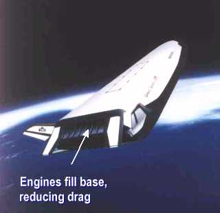 Make sure to capture data at a back-pressure ratio of 0.5283, which is the theoretical choked flow condition. ETR depends on the temperature ratio of all the other
Use proptools to find the exit velocity of the example engine: Using the isentropic relations, we can find how the Mach number of the flow varies with the cross sectional area of the nozzle. Subsonic flow, where the flow accelerates as area decreases, and the pressure drops.
engine as described on a separate slide.
engine components. Source: Shreyas Narsipur, Mechanical and Aerospace Engineering, North Carolina State University, Raleigh, NC.
The gas is homogeneous, obeys the ideal gas law, and is calorically perfect. Consider two gas states, 1 and 2, which are isentropically related (\(s_1 = s_2\)). Nozzle Analysis: Variations in Mach Number and Pressure Along a Converging and a Converging-diverging Nozzle.
Pattern 1 - Flow reaches choked condition at the throat and decelerates subsonically in the diverging section (0.8 We can determine the nozzle total pressure Compare these curves to the performance of a hypothetical matched nozzle, which expands to \(p_e = p_a\) at every altitude. The overall trends inp/pOdistribution matches theoretical trends fromFigure 3. The nozzle sits downstream of the power Copyright 2017, Matthew Vernacchia Given that the flow is choked, theMFPshould be constant. Recall that the back-pressure measurement was made at port 10. When flow is choked, the Mach number no longer increases and is capped at M = 1. In terms of Mach number, the stagnation temperature is: Because the static and stagnation states are isentropically related, \(\frac{p_0}{p} = \left( \frac{T_0}{T} \right)^{\frac{\gamma}{\gamma - 1}}\). All jet engines have a nozzle which The following example predicts the performance of an engine which operates at chamber pressure of 10 MPa, chamber temperature of 3000 K, and has 100 mm diameter nozzle throat. Mach number is the velocity normalized by the local speed of sound, \(a = \sqrt{\gamma R T}\). Values of \(C_F\) are generally between 0.8 and 2.2, with higher values indicating better nozzle performance. The trends inMFPfollow theoretical results untilpB/pO= 0.6 but start decreasing instead of plateauing for lower values of back-pressure ratios. Therefore, nozzle designers select the expansion ratio based on the ambient pressure which the engine is expected to operate in. the exit velocity Ve = V8: V8 = sqrt(2 * nn * cp * Tt8 * [1 - (1 / NPR)^((gam -1 ) / gam)] ). This is called over-expanded flow. pressure ratio, EPR. First, use the conservation of energy to relate the velocity at any two points in the flow: We can replace the enthalpy difference with an expression of the pressures and temperatures, using the isentropic relations. of jet engines, but all jet engines have some partsin common. Here, m-dot is the mass flow rate through the nozzle, T-zero is the stagnation temperature, AT is the area of the throat, and p-zero is the stagnation pressure. Then, use high-pressure PVC tubing to connect the 10 static pressure ports to the pressure measurement system, as well as the stagnation pressure port. This clearly demonstrates that the flow is choked at the throat. No flow condition, where the back-pressure is equal to the total pressure. Tt8 divided by Tt5 is 1.0. We can also determine the nozzle total It can be used to compare the efficiency of different nozzle designs on different engines. Therefore, \(C_F\) is a figure of merit for the nozzle expansion process. """, # Solve for the expansion ratio [units: dimensionless], """Compute the pressure ratio from a given expansion ratio.""". Beyond the throat exit, there is uncontrolled expansion of the flow, leading to supersonic Mach numbers. The flow pressure ranges from 0 - 120 psi and is controlled using a mechanical valve. When the stagnation pressure equals the back-pressure, there is no flow. Based on the design of the converging-diverging nozzle, the flow velocity after the nozzle throat can either: (i) decrease to subsonic velocities, (ii) become supersonic, cause a normal shock, and then decrease to subsonic velocities at the nozzle exit, or (iii) remain supersonic throughout the diverging section. As the back-pressure is further reduced, the flow after the throat goes supersonic and then subsonic. enthalpy plus the square of the exit velocity divided by two. You have unlocked a 2-hour free trial now. However, the experimental results showed the mass flow parameter decreasing for lower values of back-pressure ratio instead of plateauing once the maximum value was achieved, as predicted by theory. Please click here to view a larger version of this figure. JoVE, Cambridge, MA, (2022). The MFP increases with decreasing back-pressure ratio up until 0.6, which corresponds to expected behavior, as mass flow should increase as the back-pressure ratio decreases. Note that the first vertical dashed line on the left of the p/pO versus distance along the nozzle plot is the location of the throat, the second vertical dashed line is the location of the nozzle exit, and the horizontal dashed line marks the choked condition. Decrease the back-pressure ratio in steps of 0.1, down to a ratio of 0. This assumption is known as frozen flow. Beyond the throat/nozzle exit, there is uncontrolled expansion of the flow, leading to supersonic Mach numbers. Over-expanded flow the pressure at the nozzle exit is lower than the ambient pressure, causing the jet exiting the nozzle to be highly unstable with huge variations in pressure and velocity as it travels downstream. """, # Compute the expansion ratio and thrust coefficient for each p_e, # Compute the matched (p_e = p_a) expansion ratio, 'matched $p_e = p_a$, $\epsilon = {:.1f}$', '$C_F$ vs expansion ratio at $p_c = {:.0f}$ MPa, $p_a = {:.0f}$ kPa'. Flow after the choked condition is supersonic through the nozzle, and no shock is formed. 377, No. Open the mechanical valve to start airflow. Please click here to view a larger version of this figure. When the back-pressure ratio reaches a value of 0.5283, the Mach number at the throat is one and the flow is choked. Temperature and molar mass have the most significant effect on exit velocity. Therefore, the stagnation pressure is: Use proptools to plot the stagnation state variables against Mach number: The exit velocity of the exhaust gas is the fundamental measure of efficiency for rocket propulsion systems, as the rocket equation shows. through the nozzle) is: Notice that the mass flow does not depend on the exit pressure. Thank you for taking us up on our offer of free access to JoVE Education until June 15th. 18 May 2020 | AIAA Journal, Vol. Results for the converging-diverging nozzle (from top-right, clockwise) variation in pressure ratio across the nozzle; variation in Mach number across the nozzle; and variation in mass plow parameter with back-pressure ratio. Another common nozzle is the converging-diverging nozzle, which has a section of decreasing area, followed by a section of increasing area. We can also look at the Mach number across the length of the converging-diverging nozzle to examine flow conditions at varying back-pressure ratios. Nozzle test rig. There are two main types of nozzles: the converging nozzle and the converging-diverging nozzle. Second, flow accelerates supersonically beyond the throat and then decelerates, in some cases to subsonic velocities. It depends only on the heat capacity ratio, nozzle pressures, and expansion ratio (\(A_e / A_t\)). At the throat, the Mach number does not exceed 1, meaning that the flow is choked. Published by the American Institute of Aeronautics and Astronautics, Inc., with permission. TheMFPincreases with decreasing back-pressure ratios, peaks atpB/pO= 0.5, and starts decreasing instead of remaining constant as predicted by theory. This illustration shows two variants of an engine family, one designed for a first stage booster (left) and the other for a second stage (right). nozzle simulator program which runs on your browser. Open the mechanical flow control valve to start the airflow. losses in the nozzle, but its value is normally very near 1.0. We may use this info to send you notifications about your account, your institutional access, and/or other related products. These equations are fundamental tools for the preliminary design of rocket propulsion systems. + NASA Privacy Statement, Disclaimer, is represented by the following equation: Aeronautical Engineering. Mount the converging nozzle in the center of the nozzle test rig, as shown in. Please click here to view a larger version of this figure. Results for the converging nozzle tests showed that the maximum limit up to which flow can be accelerated isM= 1, at which point flow at the nozzle throat gets choked. If the flow is both adiabatic and reversible, it is isentropic: the specific entropy. JoVE, Cambridge, MA, (2022). For the no flow condition, again the Mach number is zero. Figure 7. the nozzle, the specific Converging nozzles, as shown in Figure 1, are tubes with an area that decreases from the nozzle entry to the exit (or throat) of the nozzle. The specific enthalpy, There are no viscous effects or shocks within the gas or at its boundaries. little algebra which you learned in middle school, and using the gas turbine engines, which are also called On completion of the tests, disconnect all systems and dismantle the nozzle test-rig. Please click here to view a larger version of this figure. As the back-pressure decreases, the Mach number increases across the converging section while decreasing across the diverging section. The velocity at the throat is: The mass flow at the sonic throat (i.e. Please click here to view a larger version of this figure. The rest of this page derives the nozzle flow theory, and demonstrates other features of proptools.nozzle. When the throat pressure ratio approaches 0. Nozzle flow theory can predict the thrust and specific impulse of a rocket engine. We also observed three types of flows that can be obtained after the choked throat depending on the back-pressure ratio of the flow. Connect the ports to the measurement system, then repeat all of the measurements as described previously. The amount of thrust produced by the nozzle depends on the exit velocity and pressure and the mass flow rate through the nozzle. Flow conditions and regimes in a converging nozzle (theoretical predictions). We use cookies to enhance your experience on our website. After this point, three distinct patterns are observed as back-pressure ratio is further reduced. The pressure ratio \(p_e / p_c\) is usually quite small. JoVE Science Education Database. vacuum) engine. Figure 5. We can also explore the variation of thrust with ambient pressure for fixed \(p_c, p_e\): We can normalize thrust by \(A_t p_c\) to give a non-dimensional measure of nozzle efficiency, which is independent of engine size or power level. As the nozzle area decreases, the flow velocity increases, with the maximum velocity occurring at the throat. We can define another performance parameter which captures the effects of the combustion gas which is supplied to the nozzle. Because the nozzle does throat area, chamber pressure, chamber temperature) and its performance (e.g. thrust and specific impulse). Larger expansions of the divergent section lead to higher exit Mach numbers. Copyright 2022 MyJoVE Corporation. Both of the nozzles tested have 10 ports, enabling pressure measurements throughout the length of the nozzle. Now, let's take a look at the converging-diverging nozzle, starting with the plot of pressure ratio and Mach number versus normalized nozzle distance. However, based on the location of the tap measuring the throat pressure (tap 9, Figure 6), we see that the measurements are taken slightly before the true nozzle throat that in turn leads to an incorrect measurement of theMFP. In this demonstration, the converging and converging-diverging nozzles - two of the most common nozzle types used in aerospace applications - were tested using a nozzle test rig. OHwyb[-d- 61g#b^K#Z]ycL`JJdOU@t0UMecQx`m%hnheY/6s* T7m3L5Hl$z)M~6l8Uhbp1Mk3o926Jrofs8qje9V5W+ wc5pc% To get started, a verification email has been sent to email@institution.com. Connect the pressure measurement system to the graphical software interface for real-time pressure data reading. We use/store this info to ensure you have proper access and that your account is secure. A JoVE representative will be in touch with you shortly. sea level) engine has a smaller expansion ratio than the second stage (e.g. As with the converging nozzle, the MFP should remain constant after reaching the choked flow condition, but we observe a decrease due to the location of the throat pressure tap. """, # Exhaust heat capacity ratio [units: dimensionless], # Exhaust molar mass [units: kilogram mole**1], # Thrust coefficient [units: dimensionless], # Characteristic velocity [units: meter second**-1], # Propellant mass flow [units: kilogram second**-1], \(\frac{p_0}{p} = \left( \frac{T_0}{T} \right)^{\frac{\gamma}{\gamma - 1}}\), 'Isentropic flow relations for $\gamma={:.2f}$'. The stagnation state is the state a moving fluid would reach if it were isentropically decelerated to zero velocity. sets the total mass flow rate through the The rocket nozzle is a flow device which accelerates gas to high velocity before it is expelled from the vehicle. The mass flow parameter versus the back-pressure ratio is also plotted and studied for both the nozzles. In jet engines, a nozzle is used to transform energy from a high-pressure source into kinetic energy of the exhaust to produce thrust. + Equal Employment Opportunity Data Posted Pursuant to the No Fear Act The following plot shows \(C_F\) vs altitude for our example engine with two different nozzles: a small nozzle suited to a first stage application (blue curve) and a large nozzle for a second stage (orange curve). The ratio between them is the back-pressure ratio, which can be used to control flow velocity. 
Sitemap 45